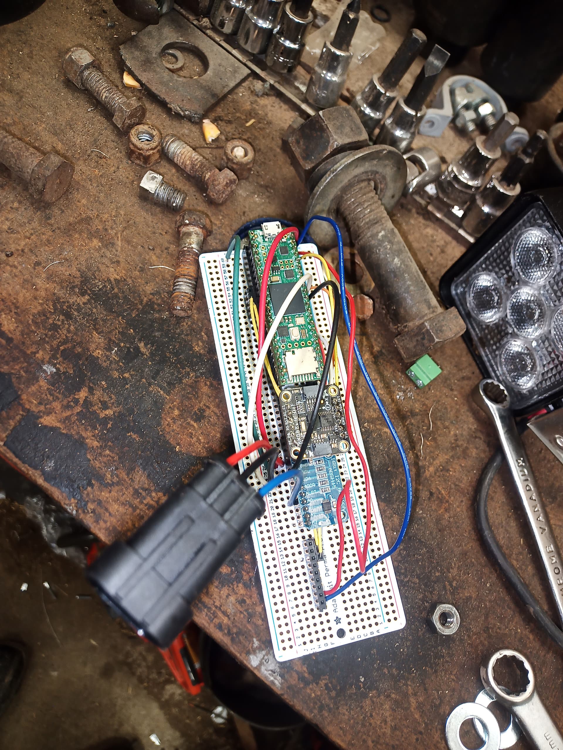
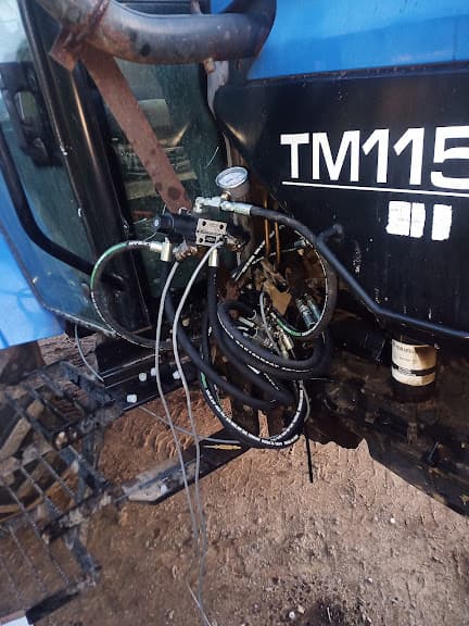
Hi everyone, I asked a while ago and got some clarification on what was actually required. Since then I have AOG up and running on a mini-PC in my TM115, along with a soldered board that matches rougly this schematic
I can confirm that it works, and I have lightbar guidance. I like agopenGPS, and it is time to move forward.
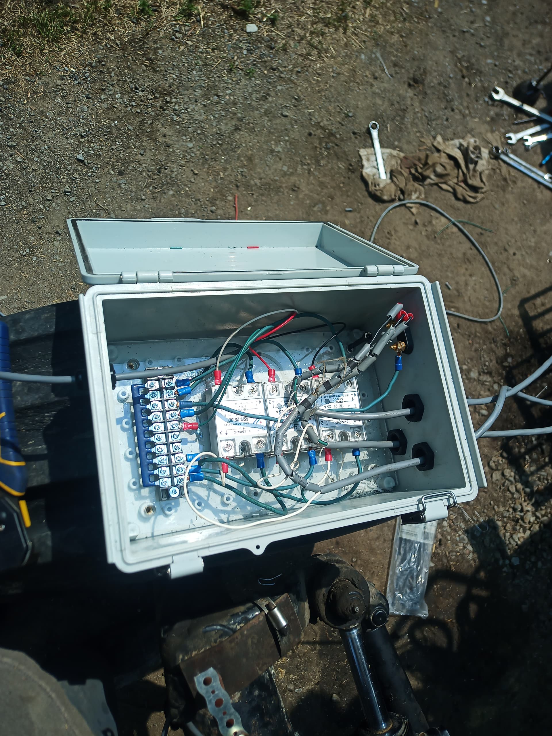
I have purchased (and installed) all the required hydraulic equipment and relays to make my tractor steer when a left/right signal is output from the teensy. (Princess Auto for the win)
I am currently in the process of fabricating a steer angle sensor using a potentiometer on the kingpin.
I realize the standard PCB version of AOG will have motor drivers on the PCB, and output a L/R signal through the ampseal connector, however I don’t have a PCB. I am looking for which pins on the teensy that will ouput these signals in the default firmware so I don’t have to reverse-engineer pcb gerbers.
I have found this section in the firmware:
//   ***********  Motor drive connections  **************888
//Connect ground only for cytron, Connect Ground and +5v for IBT2

//Dir1 for Cytron Dir, Both L and R enable for IBT2
#define DIR1_RL_ENABLE  4

//PWM1 for Cytron PWM, Left PWM for IBT2
#define PWM1_LPWM  2

//Not Connected for Cytron, Right PWM for IBT2
#define PWM2_RPWM  3
this sounds relevant to me, but I don’t understand the mapping to the physical world
//Dir1 for Cytron Dir, Both L and R enable for IBT2
this line doesn’t exactly make sense to me, should I be adding more #define directives?
I am GUESSING it means pin 2 and 3 are L&R, am I on the right track here? Are there any modifications I need to be doing to the firmware?
Also, on the ADS1115, I am assuming it expects single-ended WAS on input 1?