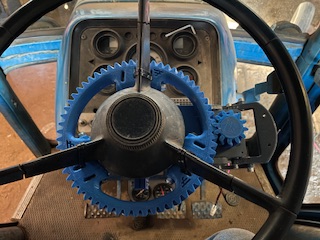
Are there any examples of the phidgits motor and steering gear in older Ford Q cabs? 7700, 8700, 9700 or early TW series. I tried searching and came up empty. Looks like the standard 3 piece gear is too small. Rides on the base of the steering wheel and would slide around getting off center. Tilt adjust lever would need to be removed as well. Just looking to see what others might have done on these older Fords.
Maybe a Keya motor and flat steering wheel might work better than a knee-knocker on that tractor.
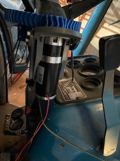
The steering column is pretty long on that model. I can make a clamp for the motor mount that will fit on the column. I didn’t. Want to modify too much on these. I would have figured someone by now had one installed on this model.
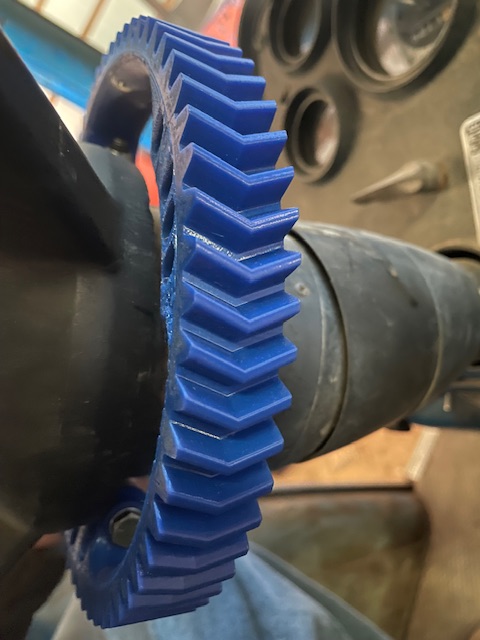
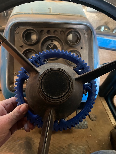
Found the larger scaled up gear and it fits on the bottom spoke of the steering wheel.
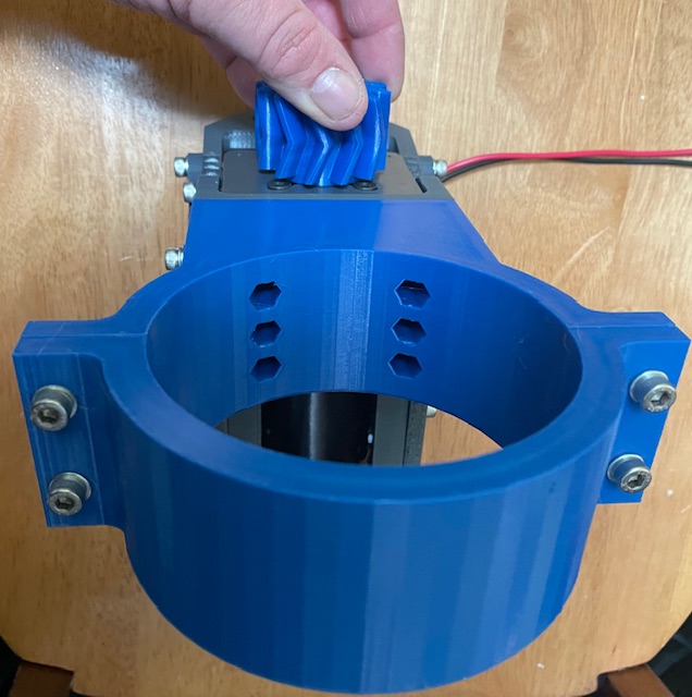
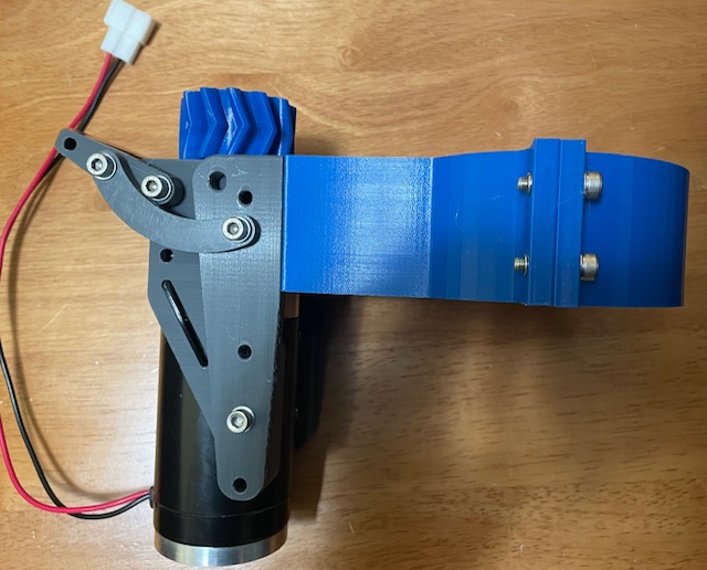
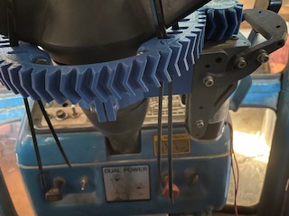
I came up with this steering column mount to fit the disconnect I found on cults3D.
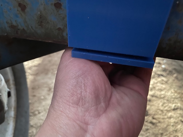
Hopefully I have the offset distance correct otherwise I’ll print shims or shave some off on the table saw I will post stls when I have it finalized. Good old tinkercad to the rescue.
2 Likes
Here it is installed. The height is perfect but might need a shim to space it out 2-3mm. Not bad for eyeballing the gap.
1 Like
nice adaption !
if you check the Cult files there is “Extra for print3D.zip” and there is spacer ( “cale”) of 2mm or 10 mm
Thanks. I forgot about that shim.
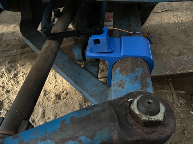
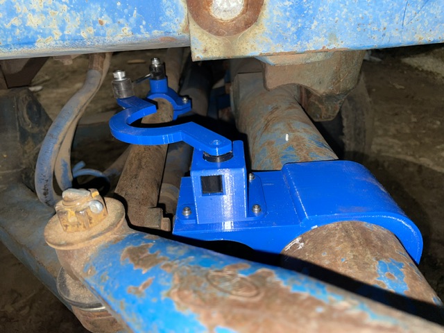
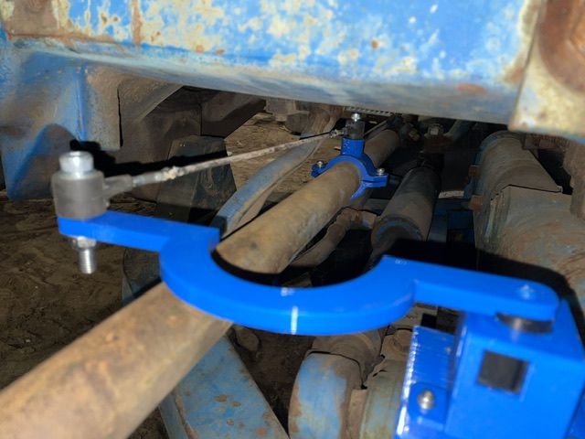
Here is my WAS bracket for the older fords. It’s offset so the pivot centers the tie rod. I have to finish the tie rod clamp yet.
2 Likes
Is the dead band at the extreme end of the steering one direction going to cause an issue? See the video on the link.
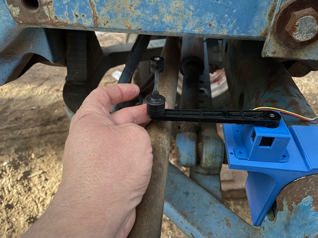
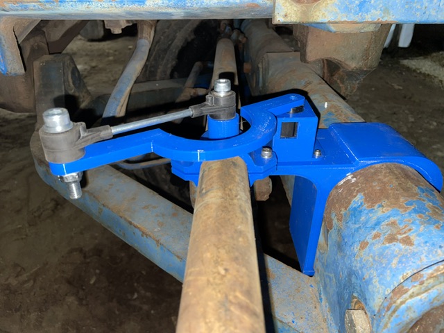
If it is not sure how to fix. Had to lengthen the arm due to the amount of travel the tie rod makes.
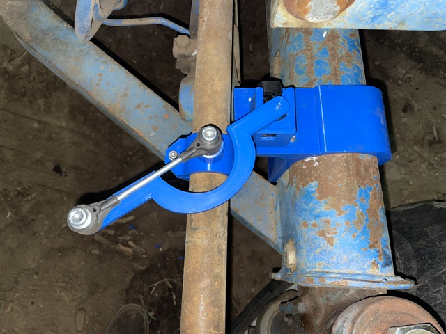
Yes it looks nice, but you have created some heavy ackermann, and will not be able to do U-turn with that deadband. Let us assume your WAS have some 90 to 120 degree working range. You can use your current setup, if you make the metal rod between your black connections triple the length it is now, so connection is further away(towards the middle og tractor, then you can use the rest of your setup, and get almost no ackermann.
Added 9” to the rod length. Looks like that took care of the dead bands.
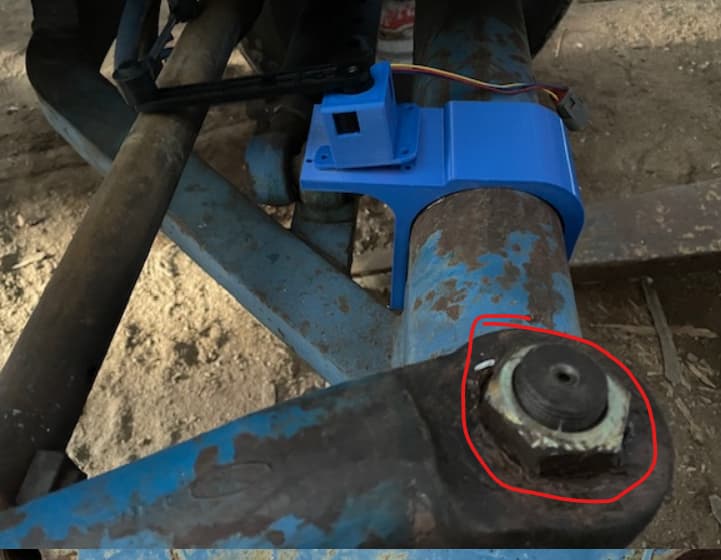
I might move it to the bottom of the tie rod since the pivot of the front axle might be a bit tight at the top.
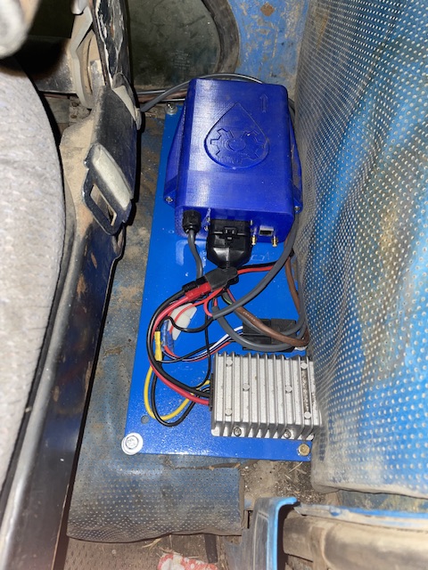
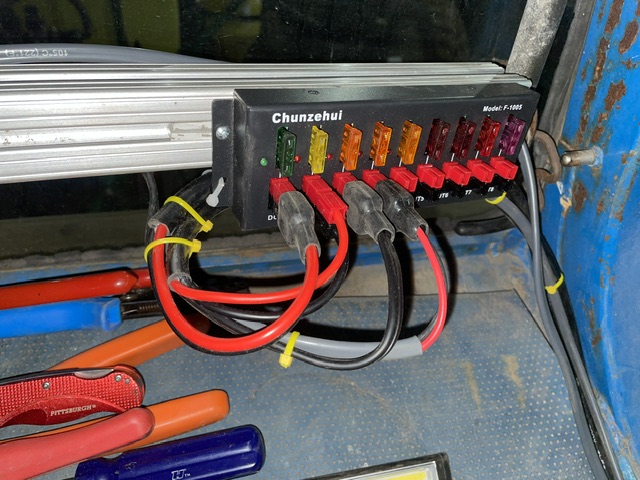
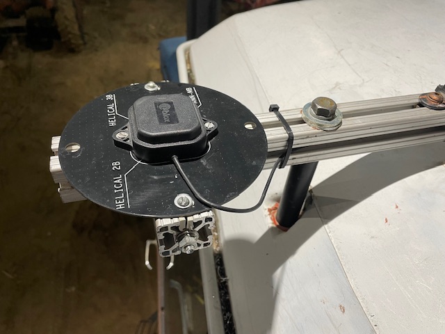
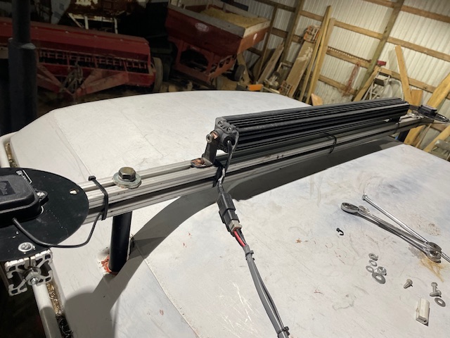
Put the 2.4 board, 12v/24v converter, and the relay on a plate next to the seat on the left side. Only area available basically. Mounted a piece of extrusion to use as a mounting bar for the tablet and power distribution. Used an Anderson power pole fuse block for power. There is room on the bar for other boxes like Raven and the boom control box for the sprayer. Planning on using a piece of extrusion for the roof to mount the antennas on n. Use a long bolt wilt a spacer for the two roof mount bolts. That way no holes need to be drilled in the roof. It will be forward the axle center.
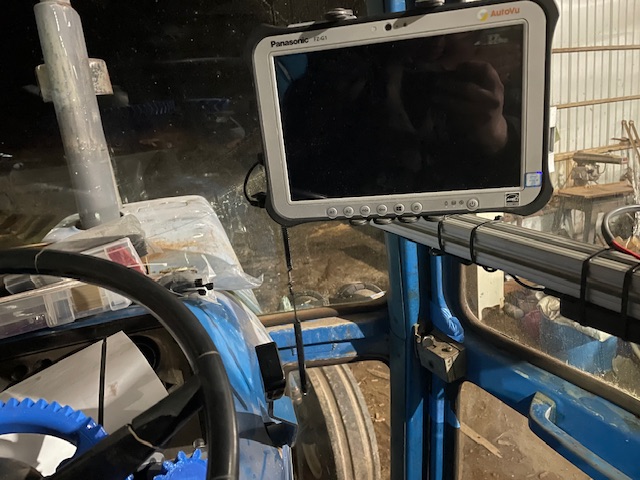
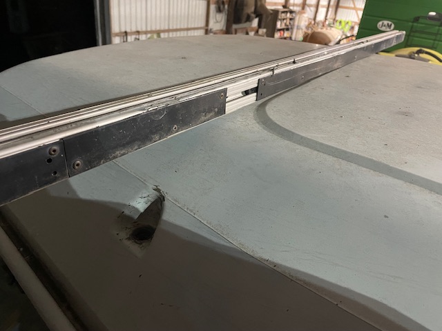
Roof mount idea. Need to get some pipe spacers and a 7” bolt. Will hold the roof and the bar. I’ll cut the extrusion the width of the cab and mount the antennas to that with screws to the extrusion. Are the metal disks below the antennas a requirement?
Hi Jason
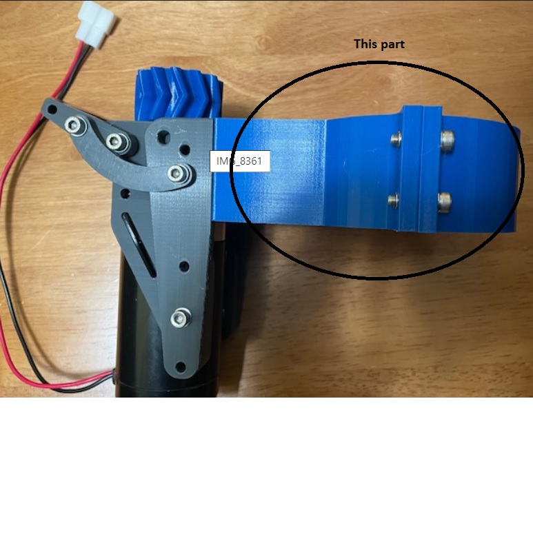
I have to do installation in Ford 8210 - can you sent link were I can find the step files you used with succes ?
Best regards, Erik
If you don’t use any ground planes you’re GPS receiver performance will be negatively affected.
Thanks but I was looking for the stepfiles to mount the gear on the steering wheel
Best regards, Erik
I widened the extrusion to 60”. Added the GND plane under each antenna. I don’t have any open fields to try it right now so I wait until wheat is off late July or early August.
I’ll upload them to thingiverse and post a link. I’ll also link the motor mount part as well that I used from Cults3D.
Hi Jason
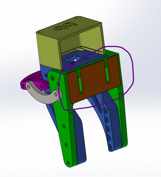
Thanks for the feedback. I looked at thingiverse and cults3D. But I was not able to find stepfile for this part. See picture.
Best regards, Erik
1 Like
Sorry forgot to upload it.
1 Like