The DAC only output from 0 to Vcc (3.3V). Internet says you must build an op-amp circuit.
I would suppose the v4 AiO board has something similar for his danfoss circuit.
The DAC only output from 0 to Vcc (3.3V). Internet says you must build an op-amp circuit.
I would suppose the v4 AiO board has something similar for his danfoss circuit.
To control the Danfoss valve I need a voltage range of 3v-9v (3.15v-8.84 to be exact from hand drawn diagram that came with the valve) 6v would have no hydraulic flow.
Could the v4 AiO board take the cut value 0-200 range from open grade3D and output the 3v-9v range or do I still need to build a op amp circuit?
I’m trying to learn how to make the 0v-3.3 from my dac amplify/scale right to 3v-9v (for example 1.65v from dac would output 6v.) not sure what the op amp circuit would look like yet.
Is there more advantages to the AiO board than just using a esp32 and a dac for grade control with opengrade3D? Like faster speeds so there isn’t a delay that causes overshooting?
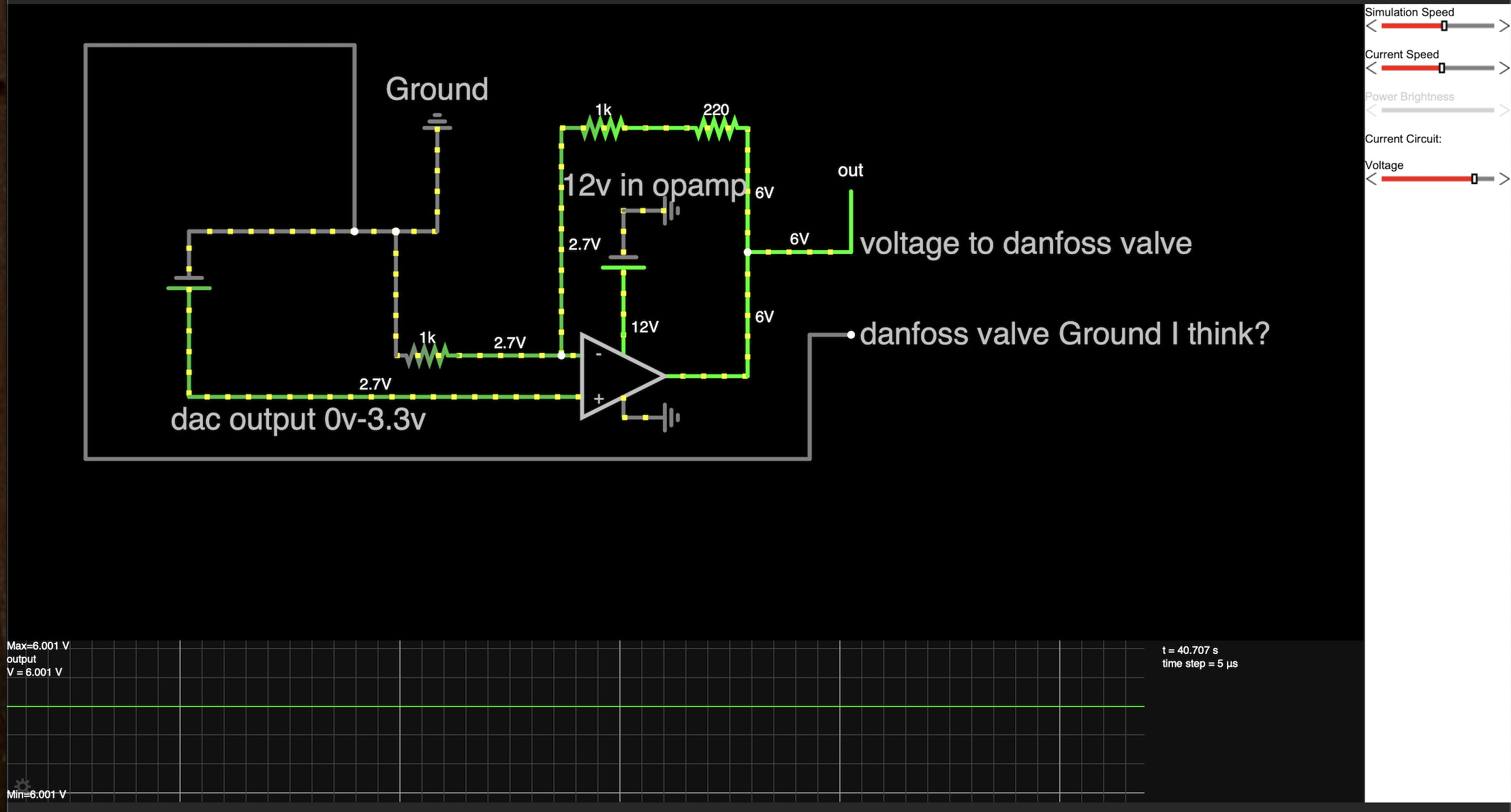
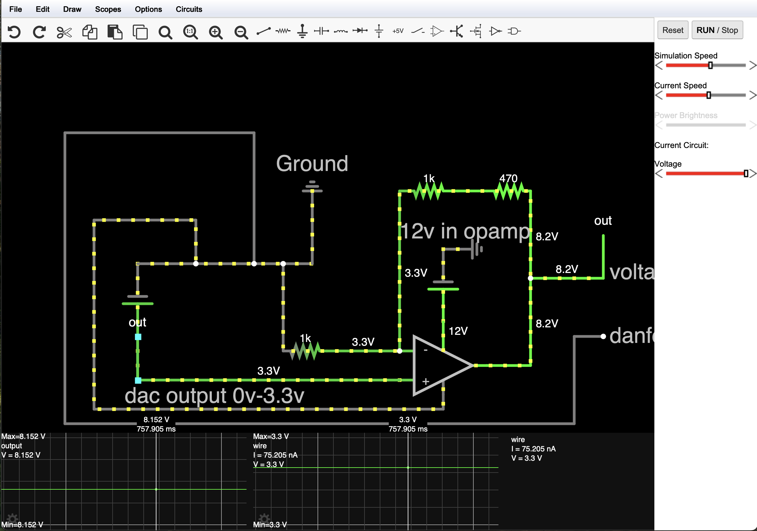
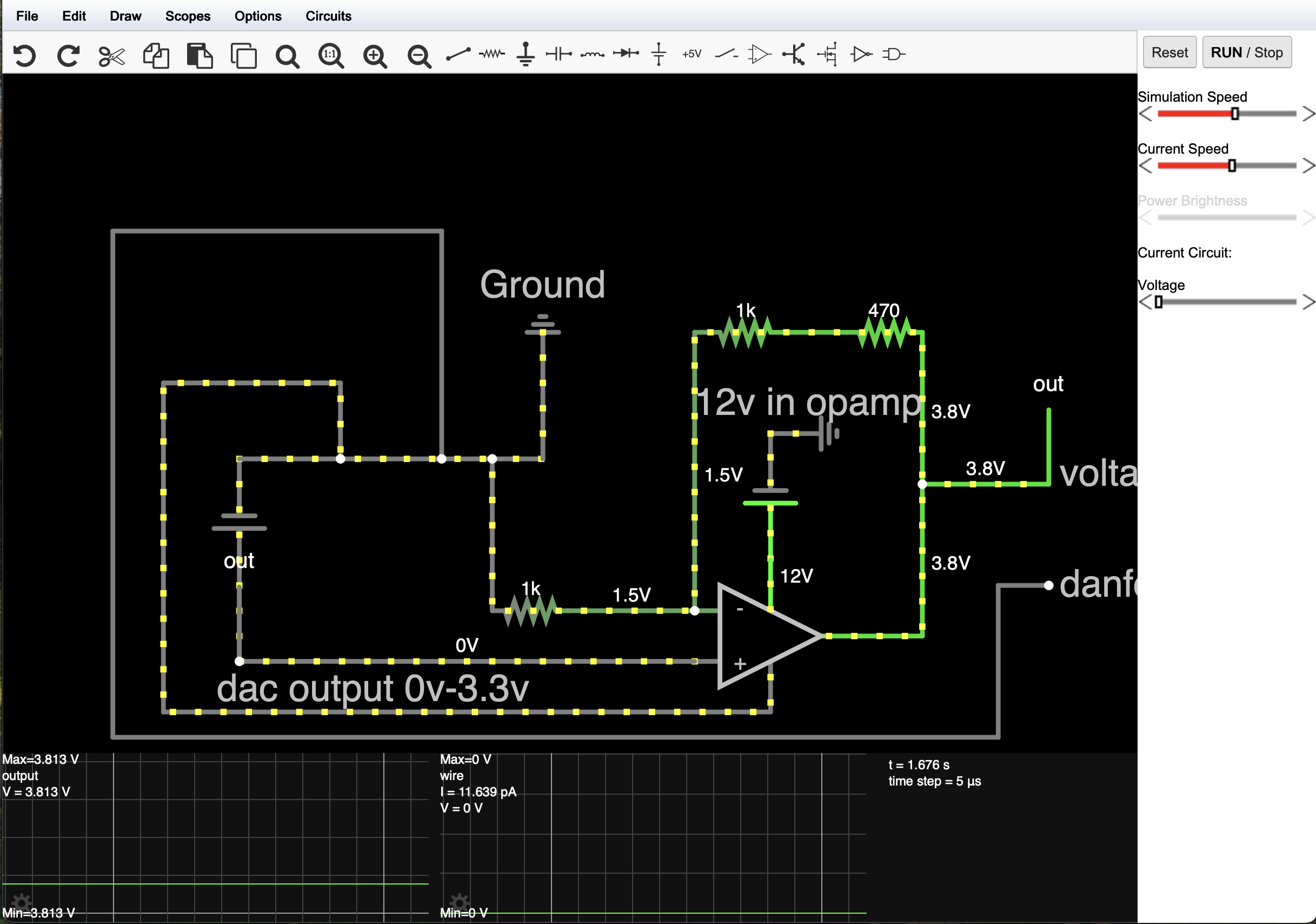
okay I think I’m starting to understand how this circuit works
Here is some video of me messing with the sim
Here is the .txt file if you want to try it in the Falstad sim
test1danfosscircut.txt (1.1 KB)
There’s no advantage about speed using an other microcontroller, even the Nano is enough.
But OG3D v4.0.2 and the corresponding ino should give better response as both had delays.
OG3D still has a timer that can cause delay but it’s 20 ms max now.
what I was trying to do was scale my variable 0v-3.3v analog dac output to 3v-9v for my valve. what I think I actually need to do is build a non inverting op amp, than scale that to my dac because I can program my dac to say 3.3v output from dac is an 8.2v output from op amp circuit and 1.4v is 3.8v because if my dac goes any lower than 1.4v the op amp still outputs 3.8, and 2.43v is 6v. I don’t think I need the whole 3v-9v range and should be fine with 3.8v-8.2v
Here is the a Video on opengrade3D vs the beta using the same code I’ve been using. Seems the beta jumps up and down the voltage more/faster? Was this intended or is it because I’m not using the right code for the beta?
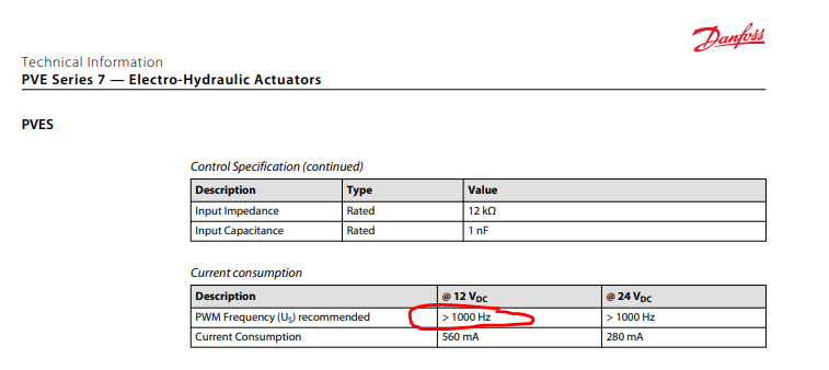
You don’t actually need an analog voltage to run a danfoss valve. You can use a simple digital PWM, but the frequency must be greater than 1000 Hz. It makes for a much simpler circuit. The AIO board works with Danfoss valves. You can copy the AIO circuits or you can drive the valve directly with an AIO.
Keep in mind also that you don’t need 3v-9v, you need 25% to 75% of Danfoss supply voltage. If you are powering the valve from tractor “12v” then it’s not actually 12v and then its not actually 3v-9v.
It’s the same ino in both?
There is no change in the data transfer.
V4.0.2 should have less delay in data transfer but should affect this way.
That would be the “overshot reduction” parameter I guess.
If you are using a custom ino maybe it is not implemented.
Interesting, I did not know you could use pwm. I don’t think I would be able to use my esp32 because it’s only 3.3v logic, I’d still have to amplify it or get a level shifter.
I don’t know much about the AiO board, but does it use something like a level shifter to output a higher pwm voltage? Or am I still not understanding and you can just control the Danfoss actuator with 3.3 logic
if I power the actuator U dc pin with 12v would neutral or 50% duty cycle always be 6v? so I would at least have to be able to output a 12v logic pwm at 50% or 6v analog to keep the valve closed?
Or maybe you just hook up pwm with a 50% duty cycle to the actuator and if the valve is still moving you adjust the pwm?
I think another thing I didn’t really understand about the valve actuator is how the voltage range works. because I was going off the hand drawn diagram from topcon and not how the actual actuator works. So if I power the actuator at 12v then isn’t 50% of the range 6v? Then 25% is 3v then 75% is 9v
What do you mean by if I’m power the valve with the tractor 12v then it’s not 12v then it’s not 3-9v. Are you saying this because there’s a voltage drop when everything is plugged in or you just meant I need 25%-75% voltage or pwm of the Danfoss valve power supply. (Which would be 12v)
Yes I was using this code for both beta and 1.0 ver of open grade3d. I did see the .ino you included with beta but I’m not sure how to implement that with my esp32 yet.
// ESP32-C6 OpenGrade Serial Communication & RGB LED & MCP4725 DAC Control

#include <Wire.h>             // Required for I2C communication with MCP4725
#include <Adafruit_MCP4725.h> // Library for the MCP4725 DAC

#define SERIAL_BAUD_RATE 38400 // IMPORTANT: Match OpenGrade's baud rate!

// Built-in RGB LED settings (assuming ESP32-C6-DevKitC-1 compatibility)
#define RGB_BRIGHTNESS 64 // Adjust overall brightness (max 255)

// PGN (Parameter Group Number) definitions from the provided code
const int PGN_BLADE_CONTROL_DATA = 32762; // 0x7FFA - Data sent from OpenGrade to Module
const int PGN_SETTINGS_DATA = 32760;    // 0x7FF8 - Settings sent from OpenGrade to OpenGrade Module

// --- Variables for Incoming Data ---
int header = 0;
int tempHeader = 0;
bool isDataFound = false;    // Flag for PGN_BLADE_CONTROL_DATA
bool isSettingFound = false; // Flag for PGN_SETTINGS_DATA

// Values received from OpenGrade
volatile byte cutValve = 100; // This is the 0-200 vertical error value (100 = on target)
volatile byte bladeOffsetIn = 100; // Blade offset value from OpenGrade

// --- Variables for Outgoing Data (Feedback to OpenGrade) ---
// These need to match the type and content expected by OpenGrade.
// For this example, we'll use placeholder/default values as we don't have
// actual sensor inputs or full control logic implemented here.
int pwmValue_out = 0;       // Placeholder for output PWM value for blade (negative for lower, positive for lift)
byte bladeOffsetOut = 100; // Our module's calculated blade offset (100 = 0 offset)
float dfValue_out = 0.500;  // Placeholder for danfoss valve value (e.g., 0.0-1.0)
float pwmValueCalc_out = 0.0; // Placeholder for internal PWM calculation value
int pwm_out = 2048;         // Placeholder for DAC value (e.g., 0-4095 for 12-bit DAC)
float pwmHist_out = 0.0;    // Placeholder for PWM history/derivative component

// Loop timing (simulating the original code's 20Hz loop)
const byte LOOP_TIME = 50; // 50 ms = 20 Hz
unsigned long lastLoopTime = 0;

// Watchdog timer for communication health
byte watchdogTimer = 0; // Increments, reset when data is received
const byte WATCHDOG_TIMEOUT_LIMIT = 30; // Roughly 30 * 50ms = 1.5 seconds without dataThe AIO uses a mosfet. It’s triggered by a 3.3v pwm pin from a Teensy and switches Danfoss Udc voltage to create Danfoss Us.
What do you mean by if I’m power the valve with the tractor 12v then it’s not 12v
The 12v electrical system of a vehicle is never exactly 12.000 volts. It typically fluctuates constantly somewhere between 12 and 15 volts, usually around 14 volts when the engine is running. If you create a perfect 6.000 volt signal and power the valve from 12v vehicle power (~14 volts), then you’re not feeding the valve a 50% signal and the valve will output.
I just realized the reason why opengrade3D beta was setpping up the voltage faster was because the sim moves the height more than opengrade 3D ver1
Just built a non inverting op amp with 12v for the input and 0-3.3v for the non inverting input. Used a 2.2k for r2 and 1k for r1. Here is a video of me testing it in opengrade. I still need to adjust the dac so instead of 5.29 being neutral 6v would be. Thanks for all the advice and help everyone. Video