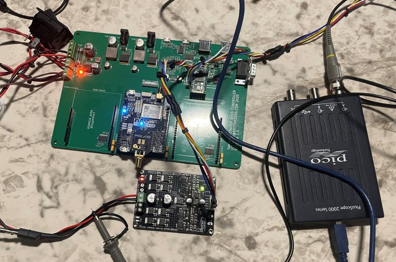
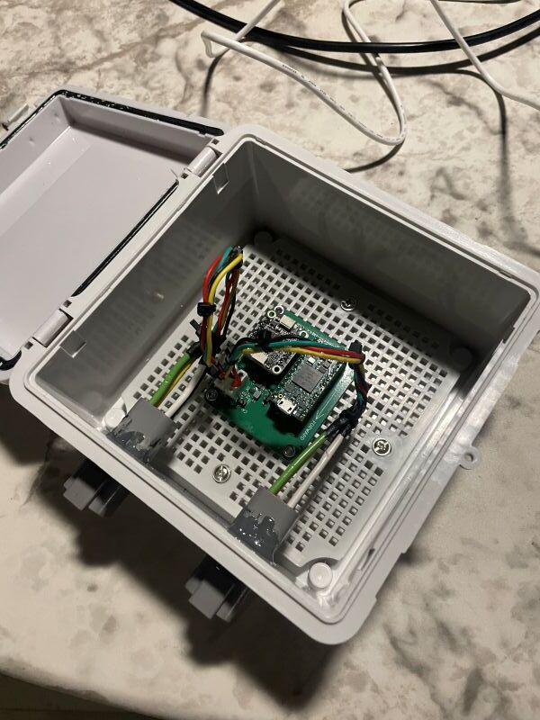
More testing. CAN bus works, Teensy works, powering a tablet and charging the battery works, PWM output to the Cytron MDD10A also works. ![]()
Andy
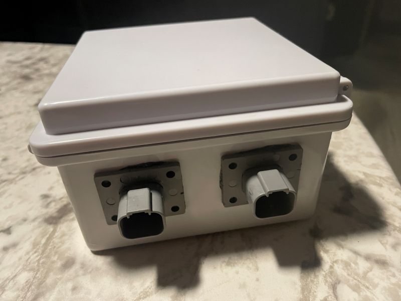
More testing. CAN bus works, Teensy works, powering a tablet and charging the battery works, PWM output to the Cytron MDD10A also works. ![]()
Andy
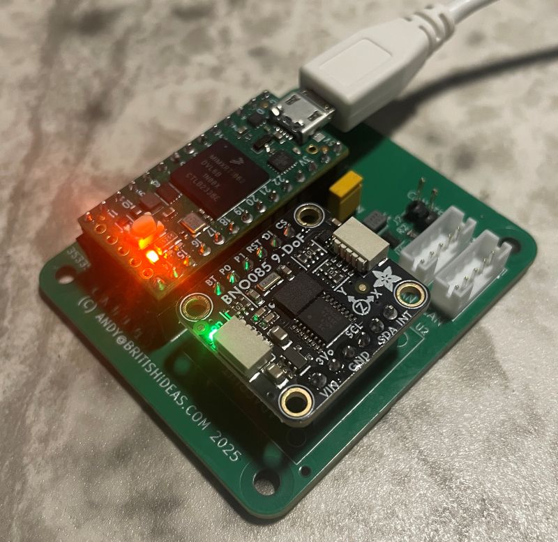
IMU is working. I have it reading out the X, Y and Z angles and the next step is to put them on the CAN bus.
Andy
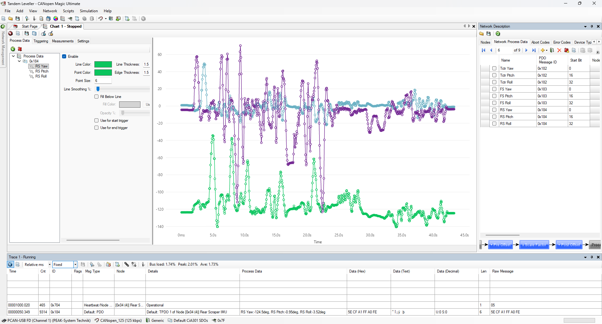
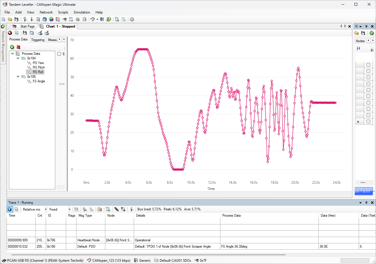
I now have the firmware for the IMU done (all will be open source once it is tested in the field). I used some parts of CANopen - NMT, PDO and heartbeats. Becaused I missed off the SDO protocol I can’t call it CANopen, but I can still use CANopen-based tools. In this screenshot I have a chart showing the pitch, roll and yaw of the IMU as I move it around in my hand.
Andy
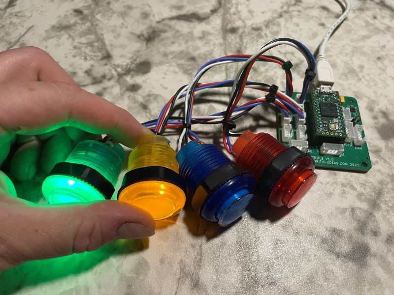
Working on the control pendant. I have the capacity for eight buttons but I can’t imagine needing that many so I will start with four.
Andy
Thinking about adding a LIDAR module to each scraper so I can get feedback on the blade height. I can easily use another Teensy 4.0 and put the module onto the existing CAN bus.
I know that an open-loop system works and people have been leveling with that for years, but something is niggling at me. If I am building a system from scratch then why not go closed-loop from the start?
Andy
How would that work? You think about measuring the actual height?
Replaced the red button with white and added an emergency stop button. Also added a second joystick so there is one for each scraper.
If the estop is hit then the controller will immediately stop automatic control of the blades. If the pendant disappears from the CAN bus for 300ms then we activate an estop (because we can’t see the estop button state).
Andy
How would that work? You think about measuring the actual height?
Monitor the change in height.
However I think it will be too dusty to use LIDAR. Maybe pulsed RADAR, I am not sure. A string potentiometer would work but they are expensive and usually require 24V to run.
Wouldn’t a hall sensor do the job, a type like the ones we use for WAS?
I’m not sure how a hall sensor could be used. However you gave me an idea. I could use another IMU bolted to the side of the scraper. I would have to work out how much the arm moves for a given blade height.
Andy
I would put the was on the scraper bucket, and the arm connection to the rear axle (measuring the movement/angle) between fully up and full down, giving something like 0.5 V at full down, and 4.5 V at full up.
Could you please give me an example sensor because the Hall sensors I am thinking of measure magnetic field. Or do you mean that a magnetic wheel should be mounted as well?
Thanks, Andy
Range Rover ride hight sensor is used much. I bought a BMW sensor. But also look for Honeywell.
I would suggest a sensor with a working range of around 90 degrees. (Most of the sensors can turn freely 360 but often have a working range between 60 and 120 degrees opposite of each other, meaning lever can be turned 180 degrees)
Here are some examples for wheel angle sensors (was)
To convert to digital if needed, ads1115 can be used
Ahhhh! I see now. I don’t row crop myself so I have never looked at the autosteer topics. This looks great. I can also take one of my spare button/joystick boards and repurpose it for this to put the angle onto the CAN bus.
Conditions for an emergency stop so far:
I asked an AI for an analysis of the OpenGrade3D code. Sure I could spend a few hours looking through it and making notes but this was quicker. Natually I will double-check the parts I need.
Andy
OpenGrade3DAnalysis.pdf (144.5 KB)
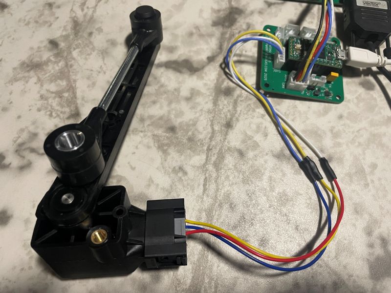
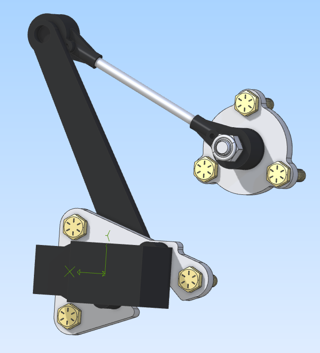
I bought an RQH100030 and a pigtail conector. I wired it up to one of the joystick inputs on my pendant board temporary, wrote some code to work out the angle and put it onto the CAN bus. Works nicely. Very smooth and no jitter.
Now to design a custom board for this CAN bus node. I’ll put one on each scraper.
Andy
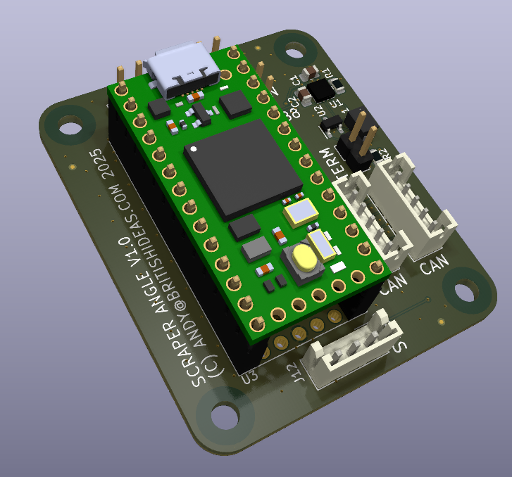
Designed a small board to calculate the angle from the ride height sensor and put it onto the CAN bus every 10ms.
Andy