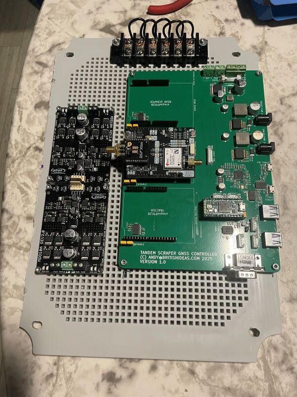
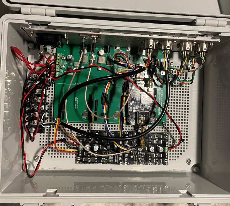
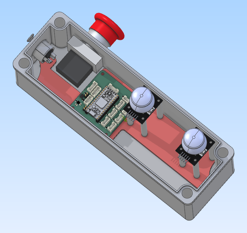
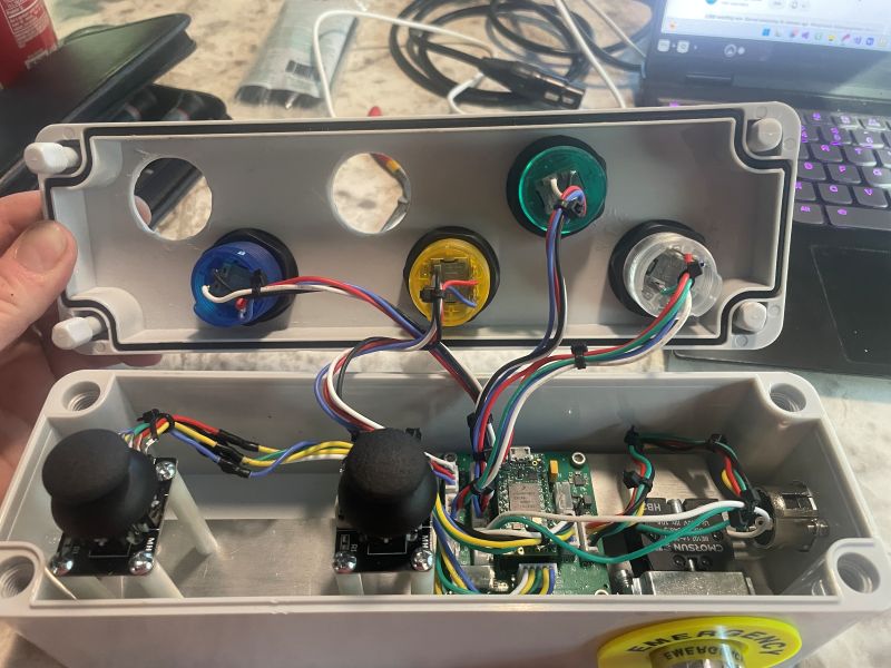
Mounted the controller board along with two Cytron MDD10A boards and a ground block into the controller box. Wired up most of the connectors on the back panel. Getting closer to being able to run something on my test mule tractor.
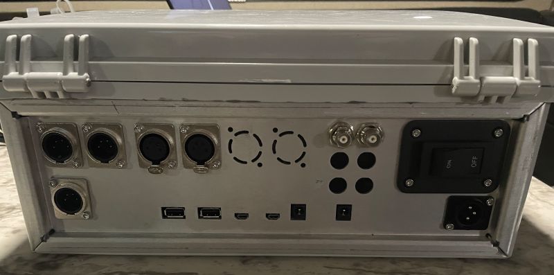
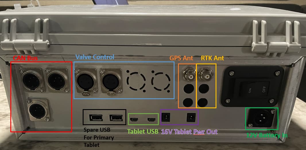
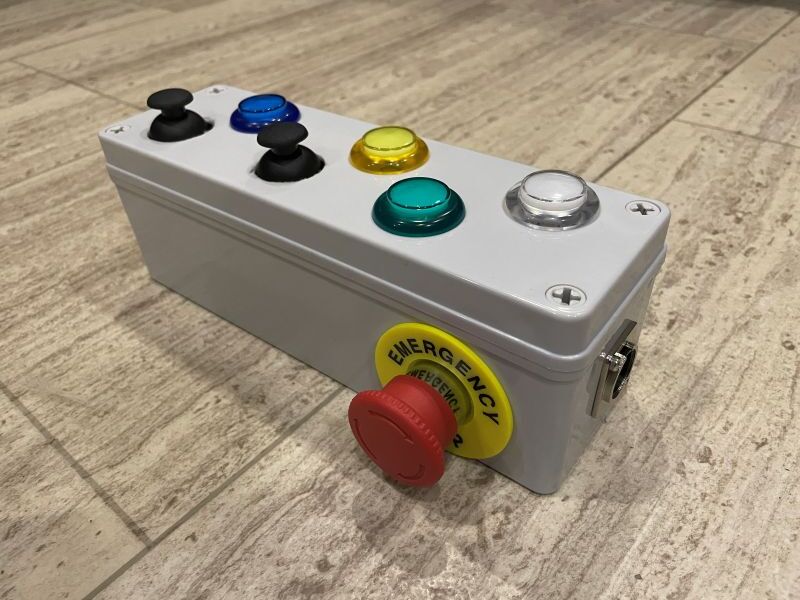
It was custom made by SendCutSend. Cost $59 + shipping. The case is from Amazon and I used a Dremel to hack a hole in the back to install it, then expoxied it in place.
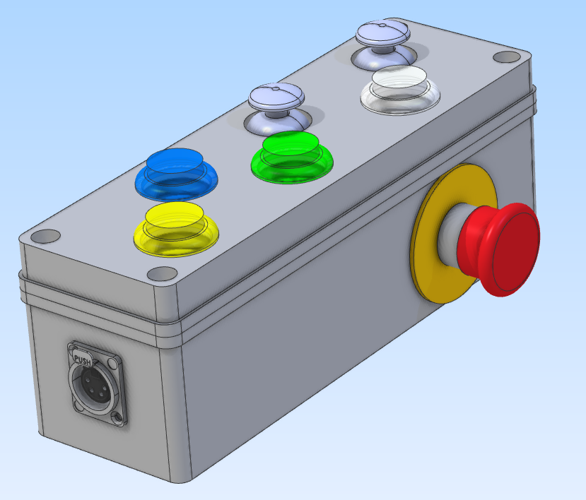
Working on the Pendant design. CAN bus connector on one end, emergency stop button on the back. One joystick and button per scraper and two miscellaneous buttons.
I am looking at the valve control arduino code. I can see that if there is a lever or up/down buttons then the user can increase or decrease a blade offset. This offset (bladeoffsetslave) is then sent to OG3D. There it is combined with the blade offset in the the right-hand panel of the main window and send back to the Arduino (bladeoffsetmaster) as well as updating the UI.
However I don’t see anywhere in the arduino code that the value is used to move the blade. I can see it is read into the variable bladeOffsetIn but then it is not used?
Am I overlooking something or was this not implemented yet?
The value is only used in OG.
I don’t remember exactly how all is written but the Arduino really only send a value that move the target this amount of mm.
The offset is really just a value added to the antenna height.
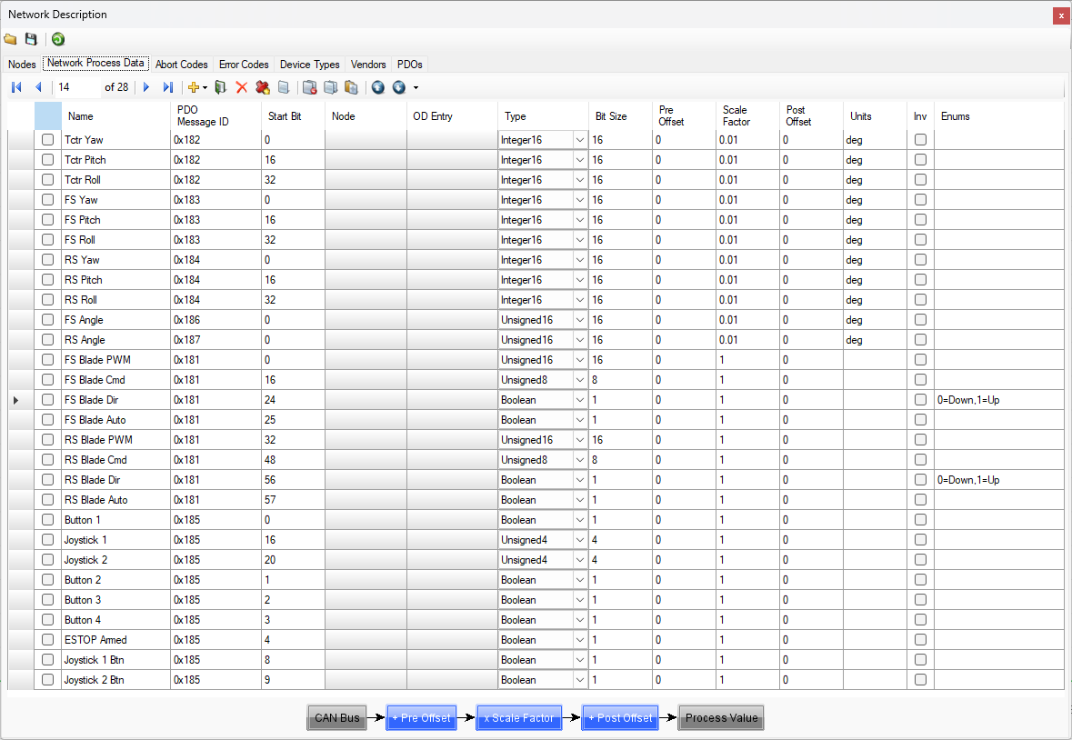
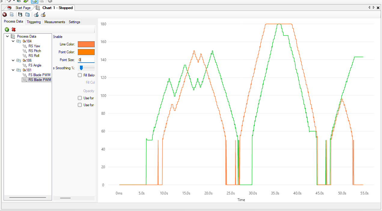
The controller now outputs the front and rear blade PWM values, the command (CutValue) values, the blade direction and whether the blade is in automatic mode or not, onto the CAN bus. I did this for diagnostic purposes so I can see the entire set of data in the system in one place.
I then set up a joystick to jog the blade up and down and charted the PWM value.
I now have jogging on both blades with the two joysticks. Each blade has a work button to toggle auto mode on or off. If auto mode is on then jogging automatically turns it off.
Here is the PWM value for front and rear blades on the CAN bus in response to jogging.
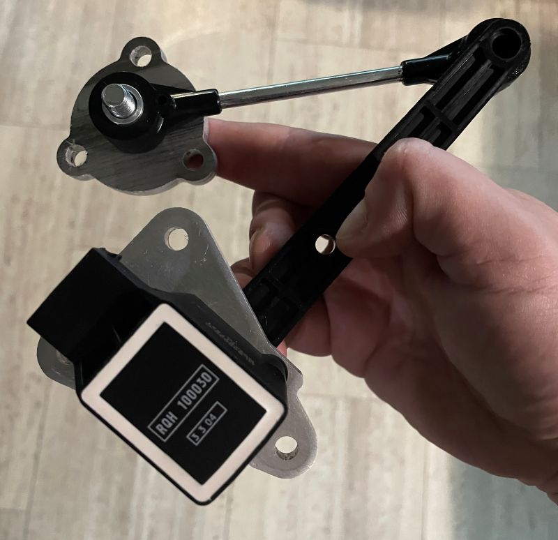
Here is my thoughts for how the angle sensors on the scrapers could be used. If anyone has any input that would be great! This would be performed at the start of each day? Or only once on equipment installation?
Drive tractor GNSS over designated benchmark point
Capture elevation of point (tractor GNSS altitude - GNSS antenna height above ground)
Pull forwards so front scraper GNSS is over benchmark point
Lower the blade to ground height (scraper GNSS altitude - GNSS antenna height above blade = elevation of point)
Measure the sensor angle
Raise the blade
Repeat steps three to six for the rear scraper
Now that I have the starting angle and a previously experimentally obtained relationship between angle and change in blade height, I can read the sensor angle every 50ms and calculate the PWM needed.
The existing OpenGrade3D sends binary data to the control board to configure it and pass valve commands and the control board sends back an ASCII string of comma separated values. I’m sure this works fine and is reliable but I decided to take a different approach.
I will use this serial packet library that is available for Arduino and C#:
This puts data into a packet with a checksum so there is a way to detect corrupted data. I will use this in both directions between OpenGrade3D and Arduino.
Each packet will contain a PGN and a 32-bit value:
// commands that are received from OpenGrade3D
typedef struct _opengrade3dcommand_t
{
  pgn_t PGN;
  uint32_t Value;
} opengrade3dcommand_t;
On top of this I have defined a PGN for pings. Every second the control board will send a ping to OpenGrade3D and every second OpenGrade3D will send a ping to the control board. This allows OpenGrade3D to be able to tell when the control board stops responding for some reason.
It will also tell the control board if OpenGrade3D stops responding and can go into an emergency stop.