Opengrade3D With Two Scrapers

I made the base station back in February using an Apache case from Harbor Freight, but I don’t like it. It uses SMA connectors which I think are fragile and hard to tell between male and female without looking closely. Also I don’t like the tripod mount - it doesn’t snug down so it is wobbly.

Here is my new idea. The simpleRTK2B and USB PSU will be in a box strapped to one of the tripod legs. I will use BNC connectors instead of SMA. Red part is sheet metal with powder coating.

Andy

1 Like

Did some driving and thinking today and decided I hate it. New version puts the GNSS antenna directly over the center of the tripod while still keeping it above the RTK antenna.

Andy

To access my controller board I have created a set of C# classes that form an API. The first is OGController that talks to the Teensy and provides a set of events when things happen. Here is an example:

OGController Controller = new OGController();
Controller.OnControllerLost += Controller_OnControllerLost;
Controller.OnEmergencyStop += Controller_OnEmergencyStop;
Controller.OnFrontSlaveOffsetChanged += Controller_OnFrontSlaveOffsetChanged;
Controller.OnRearSlaveOffsetChanged += Controller_OnRearSlaveOffsetChanged;
Controller.OnFrontBladeAutoChanged += Controller_OnFrontBladeAutoChanged;
Controller.OnRearBladeAutoChanged += Controller_OnRearBladeAutoChanged;
Controller.OnFrontBladeDirectionChanged += Controller_OnFrontBladeDirectionChanged;
Controller.OnRearBladeDirectionChanged += Controller_OnRearBladeDirectionChanged;
Controller.OnTractorIMUChanged += Controller_OnTractorIMUChanged;
Controller.OnFrontIMUChanged += Controller_OnFrontIMUChanged;
Controller.OnRearIMUChanged += Controller_OnRearIMUChanged;
Controller.OnFrontBladeHeightChanged += Controller_OnFrontBladeHeightChanged;
Controller.OnRearBladeHeightChanged += Controller_OnRearBladeHeightChanged;

Controller.Connect("COM12");

Once connected the PWM configuration can be sent:

BladeConfiguration FrontBladeConfig = new BladeConfiguration();
FrontBladeConfig.PWMGainUp          = 4;
FrontBladeConfig.PWMGainDown        = 3;
FrontBladeConfig.PWMMinUp           = 50;
FrontBladeConfig.PWMMinDown         = 50;
FrontBladeConfig.PWMMaxUp           = 180;
FrontBladeConfig.PWMMaxDown         = 180;
FrontBladeConfig.IntegralMultiplier = 20;
FrontBladeConfig.Deadband           = 3;
Controller.SetFrontBladeConfiguration(FrontBladeConfig);

BladeConfiguration RearBladeConfig = new BladeConfiguration();
RearBladeConfig.PWMGainUp          = 4;
RearBladeConfig.PWMGainDown        = 3;
RearBladeConfig.PWMMinUp           = 50;
RearBladeConfig.PWMMinDown         = 50;
RearBladeConfig.PWMMaxUp           = 180;
RearBladeConfig.PWMMaxDown         = 180;
RearBladeConfig.IntegralMultiplier = 20;
RearBladeConfig.Deadband           = 3;
Controller.SetRearBladeConfiguration(RearBladeConfig);

When the user manually lowers the blades to calibrate, the zero point can be set:

Controller.FrontBladeAtZero();
Controller.RearBladeAtZero();

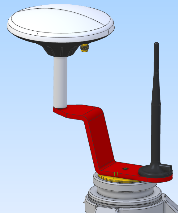
Next is the GNSSReader that gets fixes from the simpleRTK2B:

GNSSReader TractorGNSS = new GNSSReader();
TractorGNSS.Connect("COM13");
TractorGNSS.OnFixReceived += TractorGNSS_OnFixReceived;
TractorGNSS.Start();

Finally there is SensorFusor that can take a GNSS fix and combine it with an IMU reading to create a fix corrected for terrain:

/// <summary>
/// Got a new position fix for the tractor, fuse with latest IMU reading
/// </summary>
/// <param name="Position">Current tractor position</param>
private void TractorGNSS_OnFixReceived
    (
    GNSSFix Position
    )
{
    SensorFusor Fusor = new SensorFusor();
    GNSSFix TractorPosition = Fusor.Fuse(Position, CurrentTractorIMU, TRACTOR_ANTENNA_HEIGHT_CM, TRACTOR_ANTENNA_LEFT_CM, TRACTOR_ANTENNA_FORWARD_CM);

    Console.WriteLine(string.Format("Tractor: {0} {1} {2}m {3}",
        TractorPosition.Latitude, TractorPosition.Longitude, TractorPosition.Altitude,
        TractorPosition.HasRTK ? "RTK" : "No RTK"));
}

The IMU readings are sent every 50ms so when the GNSS fix is received it will use the IMU reading immediately preceding the fix.

Next step is to integrate this into OpenGrade3D.

Andy

2 Likes

Does it matter if the tractor’s IMU is on the roof or inside the cab? I am thinking it doesn’t matter because the pitch, roll and heading is always the same for the entire tractor.

Andy

1 Like

I prefer to keep it low, inside the cab - less susceptible to over-exaggeration that way.

1 Like

I think low is better as well.

1 Like

Thanks guys! I guess I will do the same with the scrapers as well - mount them on the front of each one rather that up high with the GNSS antenna.

Andy

1 Like

PC software project is here: AgGrade

Andy

Currently the architecture looks like the block diagram I posted at the beginning - the CAN bus and the rovers/NMEA-0183 are funnelled to a USB hub which then connects to the primary tablet. When the tablet is connected it sees multiple COM ports.

I now understand that USB is not reliable enough for use in a tractor so I will switch to Ethernet/UDP. However redesigning my controller board would be very expensive, so I don’t want to do that.

Instead I will design a single adapter board that can convert it from USB to UDP.

The adapter board will plug into the Teensy 4.0 socket and allow a Teensy 4.1 to be plugged into it. The board will have an RJ45 connector for connection to the tablet.

Fortunartely I designed into my board a “GPS Sim” connector. The original intention was to have an external simulator board that plugs into this connector and creates fake NMEA-0183 messages. However I can reuse this to supply the NMEA-0183 messages to the new adapter board instead. Now instead of the GNSS data going directly from the simpleRTK2Bs to the tablet via USB, they will go to the new Teensy 4.1 and then over UDP to the tablet.

My original intention was to have two tablets - master and slave - so I could run OpenGrade3D on one and a haul route planner on the other. Now that I am developing my own software - AgGrade - where the haul planner could be integrated - I am not sure I will use a second tablet, but I don’t want to lose this option for the future.

On the current board the two tablets communicate via USB. They both have a virtual COM port that connects to the other tablet. If I am eliminating USB then I won’t have this.

So my plan is to put two Teensy 4.1s onto the new adapter board, one for each tablet. Then each tablet has an RJ45 connector and the tablets can communicate via a serial link between the two Teensy 4.1s on the adapter board.

Because I already have my connector panel designed and attached to the case I will use short RJ45 panel pigtail connectors to bring the adapter board RJ45s out to the connector panel. All that is required is the drilling of two new circular holes.

Andy

2 Likes

Here is the UDP adapter board. It plugs into the Teensy 4.0 socket and provides two Teensy 4.1s.

And here it is installed in the case with the main controller board.

Andy

2 Likes

New base station box designed. Contains a simpleRTK2B, a USB battery pack and two BNC connectors. The red part is a plastic insert that protects the board. The case is off-the-shelf IP67. Will get sendcutsend to make the plastic insert.

Andy

An updated list of possible improvements to the controller board. I don’t have plans to do these but putting this here in case I change my mind:

  • A set of 10 ground screw terminals on the controller board to avoid needing a seperate teminal block
  • Remove USB hub, transceivers and connectors
  • Integrate the UDP adapter onto the board (replace Teensy 4.0 with 2x Teensy 4.1)
  • Integrate an IMU onto the board
  • Replace the valve and CAN bus connectors with a single large connector with enough pins to support four valves
  • Allow 2x Cytron MDD10A to be mounted onto the board?

Andy

1 Like

I found a side profile drawing of a Reynolds 8C scraper from Reynolds literature. I imported this into my CAD software and scaled it to a length of 5.94m (hitch to back of tires).

I then traced over it a set of lines with constraints. The hitch point is anchored and the relationship between points on the body and the hitch never change. However the assembly for the axle can move as the length of the line representing the cylinder changes.

I draw a line to represent the ground with a drawbar height of 47.9cm and then measured the blade to the ground as I changed the length of the line representing the cylinder.

At the same time I measured an angle between the body and the rear axle assembly.

I put this into Excel and got a linear relationship.

For every cm change in blade height the angle changes 0.7066 degrees.

The angle change between 0cm blade height and -6cm (the max cutting depth I will use) was 8.49 degrees.

Of course the drawing is probably not accurate, the drawbar height is probably not accurate and where I picked on the drawing for the blade to be may be wrong, but I just wanted to get a rough idea of the relationship.

Does anyone know the repeatable accuracy of the RQH100030 Land Rover ride height sensor?

I’m now wondering if there are mechanical ways to exaggerate the angle. That would increase resolution, as I would only be using 10% of the range of the RQH100030.

Andy

2 Likes

Well scratch all that! I don’t know why I didn’t realize it before, but the ride height sensor measures linear displacement, not angle. It converts the linear displacement to an angle only for measuring.

It seems I can use it to measure a range of about 180mm, so I just need to find a spot on the sides of the scrapers where the distance increases and decreases as the blade is raised and lowered. Should be doable.

Andy


Or if you need a little longer 3D printer a longer arm on the sensor.

1 Like

It would be very useful if my AgGrade software could tell when soil is being dumped, however I am wondering how I could tell it this.

For dumping I will need to operate one remote lever for each scraper and do it manually. Some ideas:

  1. Press a button on the pendent whenever I start and stop a dump. This is the simplest but requires me to remember to do it.

  2. Add software control for the dumping. My hardware can handle four valves but that would be another $1600 investment in the valves.

  3. Attach a microswitch to the tractor remote levers. Has anyone done something like this before? Is it even feasible? This would be easy to add as I can repurpose one of my existing CAN based I/O boards and put the two microswitches onto the CAN bus. I could 3D print brackets.

Any other ideas? I am currently leaning towards option three.

Andy

Are they ejectors? Linear pot on ejector cylinder.

1 Like

No they are not, but you have given me the idea! I just have to attach an IMU to each bucket then compare the pitch of the bucket with the pitch of the scraper to determine when it is dumping.

Andy

1 Like

One Idea I had while doing my own scraper operations is a “end dig” hot button. The button would simultaneously close the apron and raise the bowl to max height. Thinking it through I wonder if it couldn’t just be a timed function instead of home switches that would need adjust and would be prone to failure. Its something I am always checking on my way to dump that the apron is tight and I’ve raised the bowl enough would help with repetitive fatigue

1 Like

I was thinking about what could be done along these lines last night. Controlling the apron would require another valve though. Now that my software can calculate how much dirt is in the front scraper I was thinking that I could have it automatically raise when full and then lower the rear scraper. Then when the rear scraper is full automatically raise it. That would make the tandem cutting operation a single button press.

Amdy

2 Likes