I bought my xbee radios from ardusimple and whatever configuration they have works with as many rovers as you like.
2 Likes
Any chance you can connect XCTU and read out the settings so we can see how they are configured?
On the simpleRTK2B does the XBEE->GPS LED flash once a second or once every few seconds?
With a base station already powered up for a while, how long does it take your rovers to go from power on to RTK fix?
Thanks, Andy
https://discourse.agopengps.com/t/digi-sx-pro-ardusimple-lr-xlr-radio-compatiblity/5571?u=tfriesen. I think this may be the info you’re wanting
Looks like that is for the XBee SX? I am using the XBee 3.
I thought you were talking about the sx radio. I don’t know anything about the ones you have.
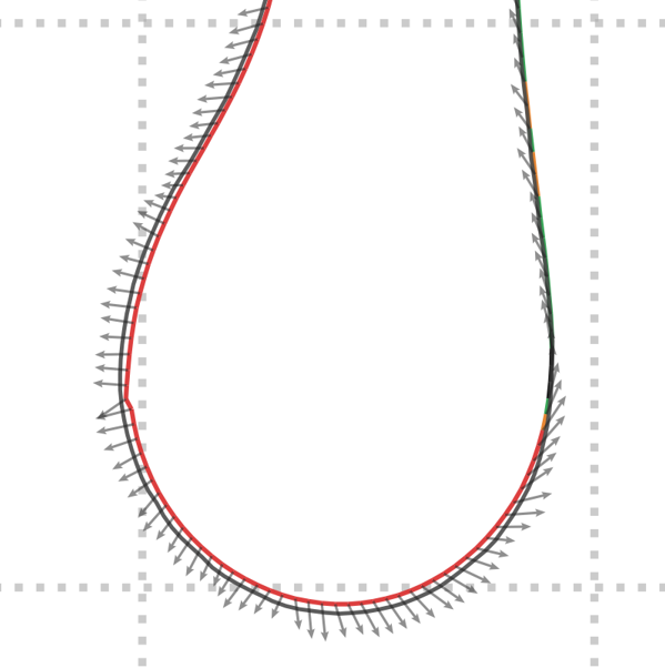
Some sensor fusing test data from driving. Here the grey line is the antenna location, the red line is the fused antenna location and the arrows indicate the direction of roll + pitch and the size of the roll and pitch. In this case it picked up the body roll of my vehicle as I turned, which pushed the antenna out from the turn. The sensor fusing code in the Teensy corrected the antenna location back inwards.
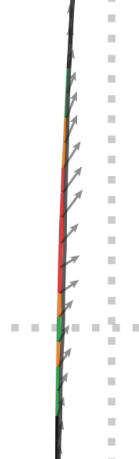
Driving through a small dip.
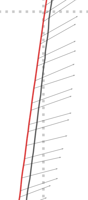
Driving with the right side of the vehicle going through a large depression.
Andy
2 Likes

3 Likes
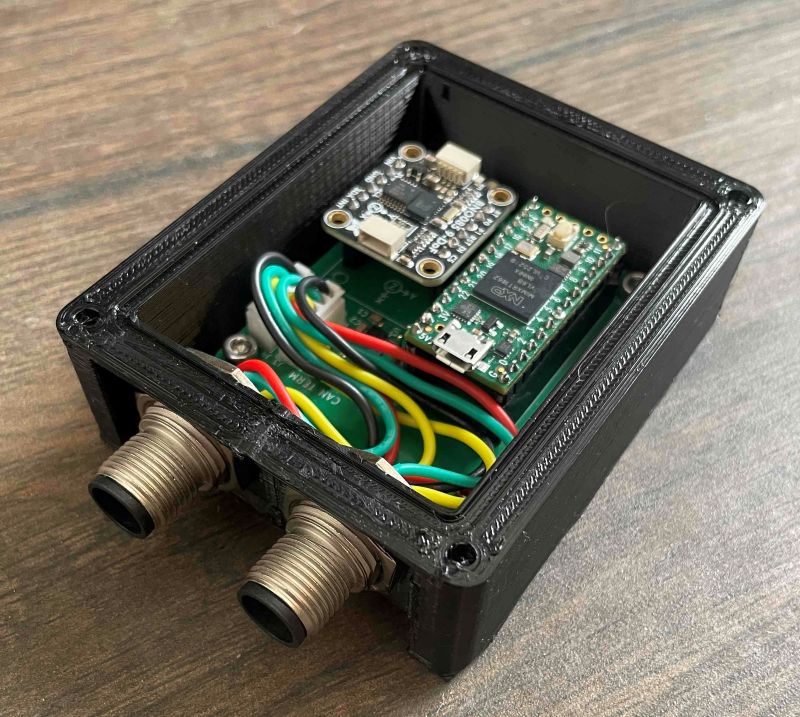
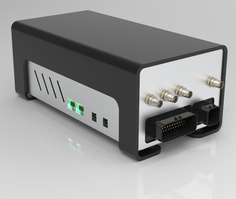
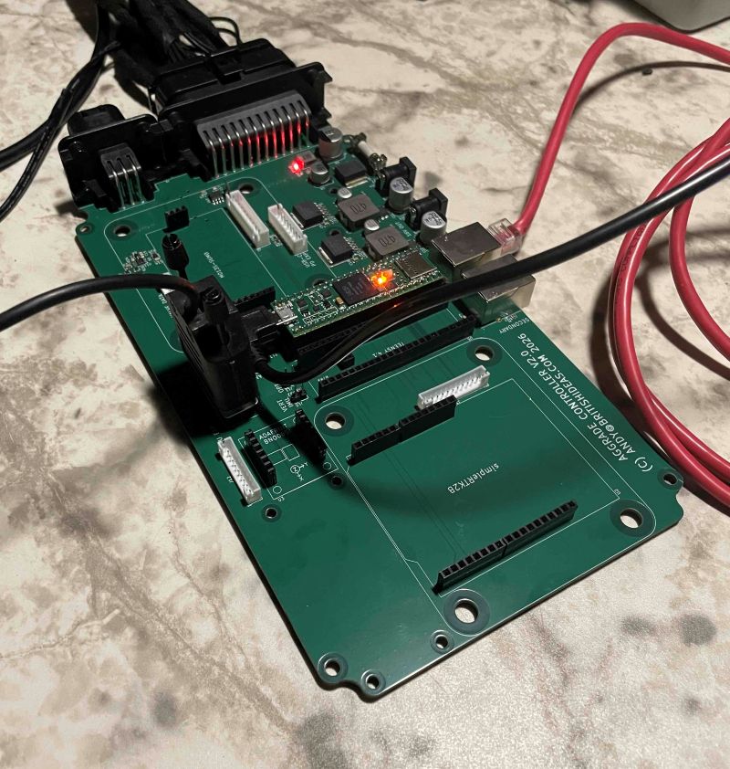
V2 IMU. This housing is printed in PETG which I will use for validation but later the plan is to have them CNC machined in aluminium. Uses M12 connectors. Andy
2 Likes

3 Likes
Nice process!!! Thx for share!!
2 Likes
Hey @Pat - in OpenGrade3D I copied the PWM settings for PWM gain (3 down, 4 up) and PWM min (50) and PWM max (180).
By my calculations that gives a blade movement range of:
Lowering (PWMGainDown = 3): 130 / 3 = 43.3 mm
Lifting (PWMGainUp = 4): 130 / 4 = 32.5 mm
Did you develop and test OpenGrade3D with a servo rather than a proportional valve? I think that is what is tripping me up here. I am using a proportional valve so that means as the target blade height is approached the PWM value has to come back to 50% duty cycle to stop the motion.
I.e. PWM value = speed, not distance
Thanks, Andy
These settings are for the MCU to calculate the needed PWM, they all are just factors.
OG3D send the distance from target in mm.
The controller has to calculate the valve movement with some PID, especially since there’s a fair delay until the target height reach the MCU after the position reading.
I hope to improve that significantly by sending the target height instead. This way the teensy will be able to adjust the PWM as soon as the GNSS is read
1 Like
OK thanks, I understand now.
I hope to improve that significantly by sending the target height instead. This way the teensy will be able to adjust the PWM as soon as the GNSS is read
That is my aim with the angle sensor. The GNSS provides a target every 200ms and the Teensy operates a fast closed-loop system.
Andy
2 Likes
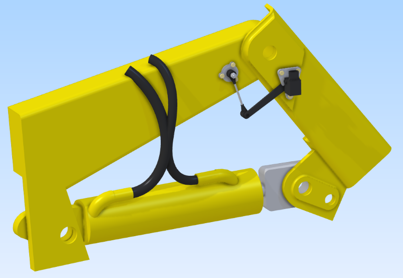
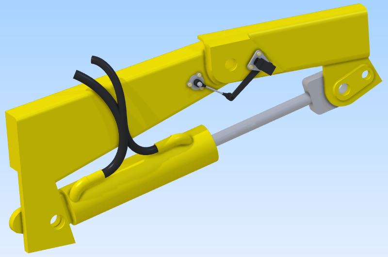
Does anyone know what this valve(?) is on the front of my scraper? Some kind of pressure relief?
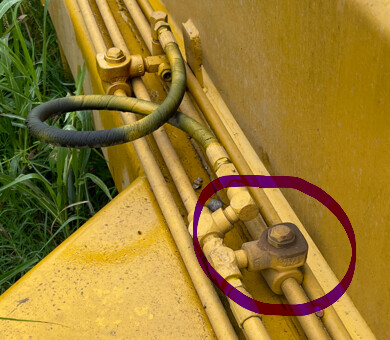
Thanks, Andy
The only thing that comes to mind is if one valve controls two functions. On my scraper the apron and plunger are on the same valve. This valve may insure that one function strokes before the other with no resistance to either function
1 Like
Thanks! That must be what it is. Andy