Hello,
I just wanted to document my attempt to build a AgOpen-Setup based on passive PoE. Each larger step will be an own update post.
But first a bit “why” and what I hope to archive.
Why:
- Ethernet: Avoid all the problems USB has with grounding. Also no trouble with changed numbering of COM ports and such.
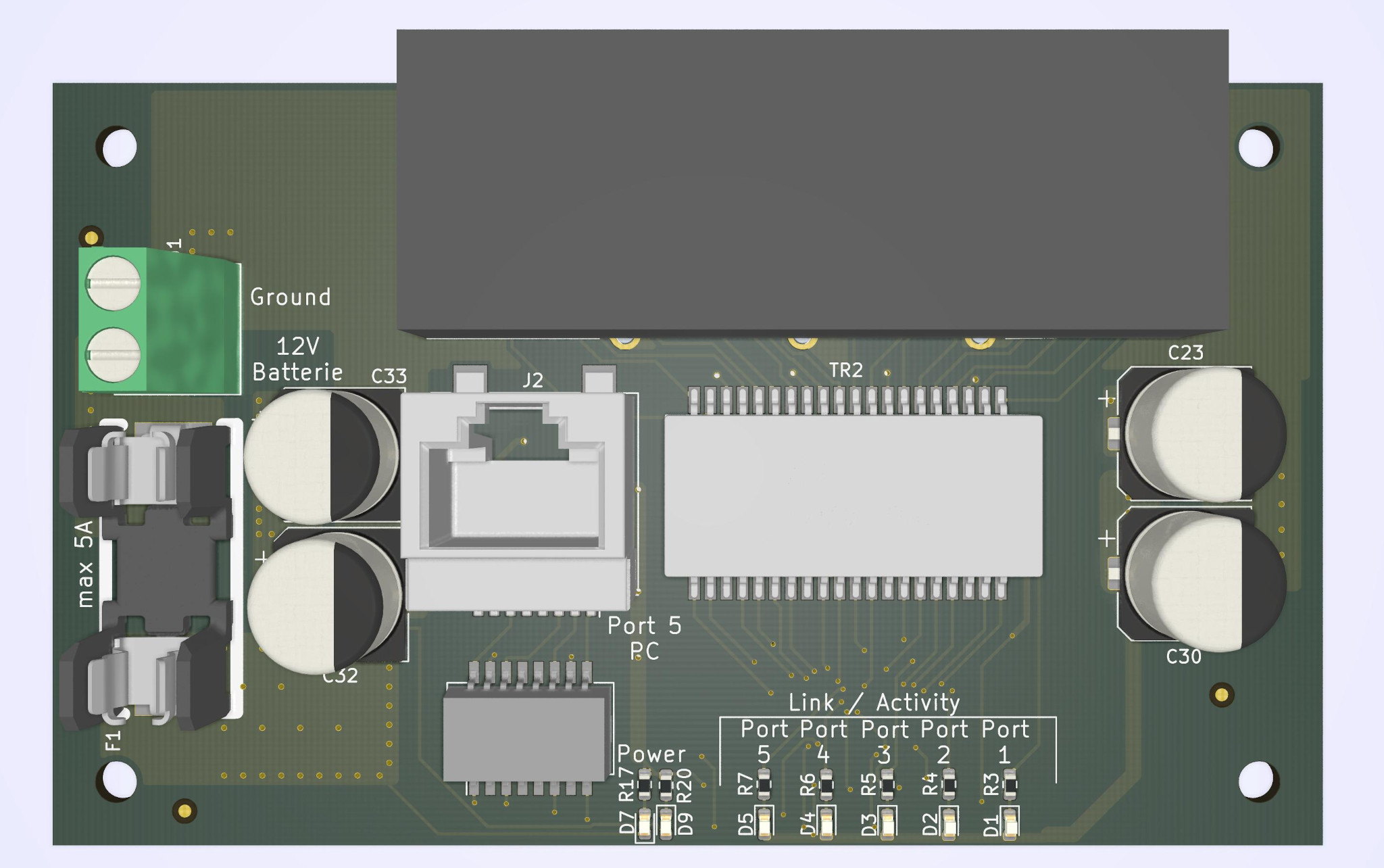
- Passive PoE: Easier cabeling and the option to move the device easy from one machine to the other. Passive PoE and not 802.3 compliant PoE since that would require step up and step down converter and special ICs, that would introduce additional complexity. Over the short distances in a cab, 1A/12W on each switch port is not a real problem, and sufficient for the most applications.
- Modular: Why not one of the “All-In-One PCBs”? I even designed one myself that is currently running! Mainly the same reasons as before. Fixed to one machine, not easy to modify or extend.
- I can learn new stuff

What:
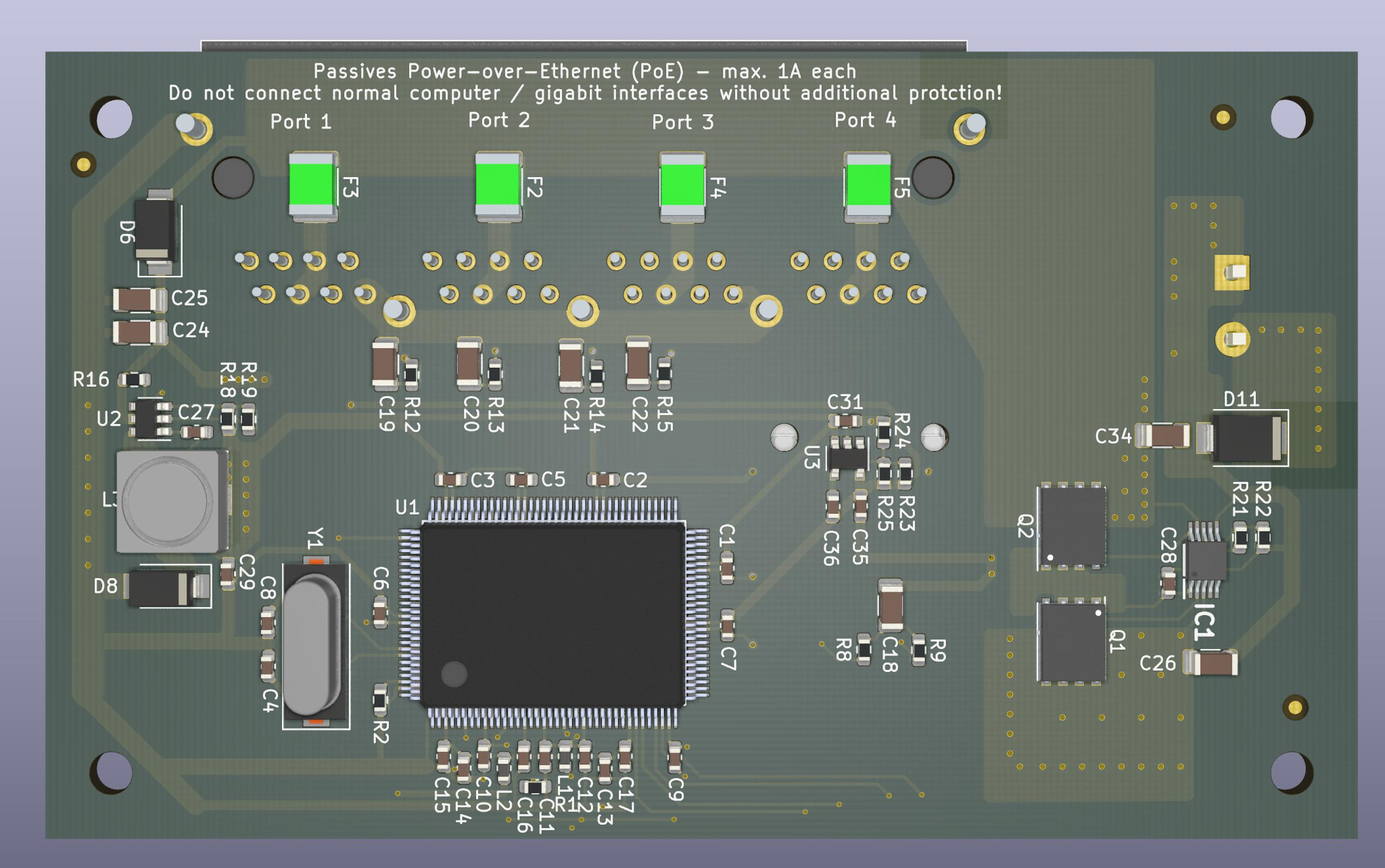
- A switch: Besides learning there are two reasons why I decided to design my own switch and not just use a cheap Chinese one:
- Better design to deliver current. The modules I bought had quite thin traces for the power supply of the attached devices.
- Better protection. Add fuses, over voltage protection and an “ideal diode” to optimize power supply.
- A (stepper) motor controller for steering.
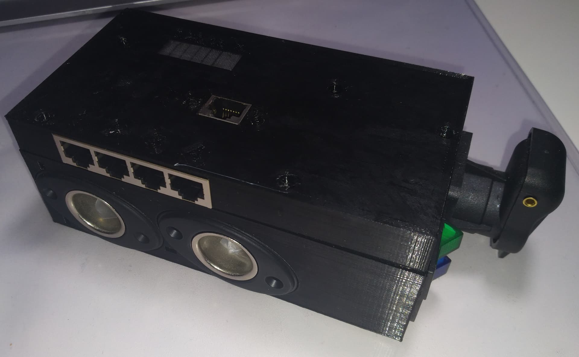
- Sized that it fits on the back of an Nema 17 stepper, so it results in a cute little unit.
- connected to the switch only over a single Ethernet cable
- planed with a virtual WAS using a magnet field sensor to detect turning while motor is disengaged
- Also use that sensor to detect if someone manually turns the steering wheel to disable steering
- Single/Dual GPS with integrated LTE modem (SIM7600 in pcie form factor) so ntrip data can be acquired without the need of a additional router or mobile hotspot.
- Light bar: When manual steering is used for whatever reasons. bases on WS2812B LEDs
- One or two controls for implements.
Basically in that order more or less. Switch should have reached now final design, but I need to assemble and test it. Motor controller has a working design where minor improvements are planed. Software development just started. GPS has a first design, that has multiple known flaws, no software yet.
Will update the thread from time to time when the different components have some progress.