Hello,
This is my PCB do I am missing something in the PCB? I understand I need jumpers, do I need something more? I will use 24V Phidgets motor.
- I seen some people have components here, someone not, how is it really?
- I seen what this type of board need free wheel mod here, but free wheel mod can be done in the MD13S. Do I need do only one mod or in both components?
THANK YOU!
[image]
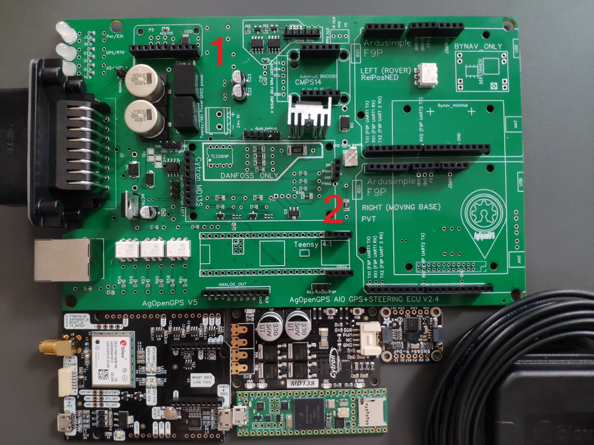
Number 1 your ok as the capacitors are already soldered on
Number 2 is where the free mod is done on the cytron but if you use the relay option to disengage you won’t need to modify anything.
The blue circles you will need some ethernet pins on the board and the teensy, they are a block of 3x2 2mm headers pins.
You will need a screw terminal soldered to the 24v in holes
And also the 24v pads need soldering
You will also need some jumpers on the header pins infront of the cytron
2 Likes
Hello, i don’t want to crate new topic ensure cleanliness in the forum, so I will write here.
1.
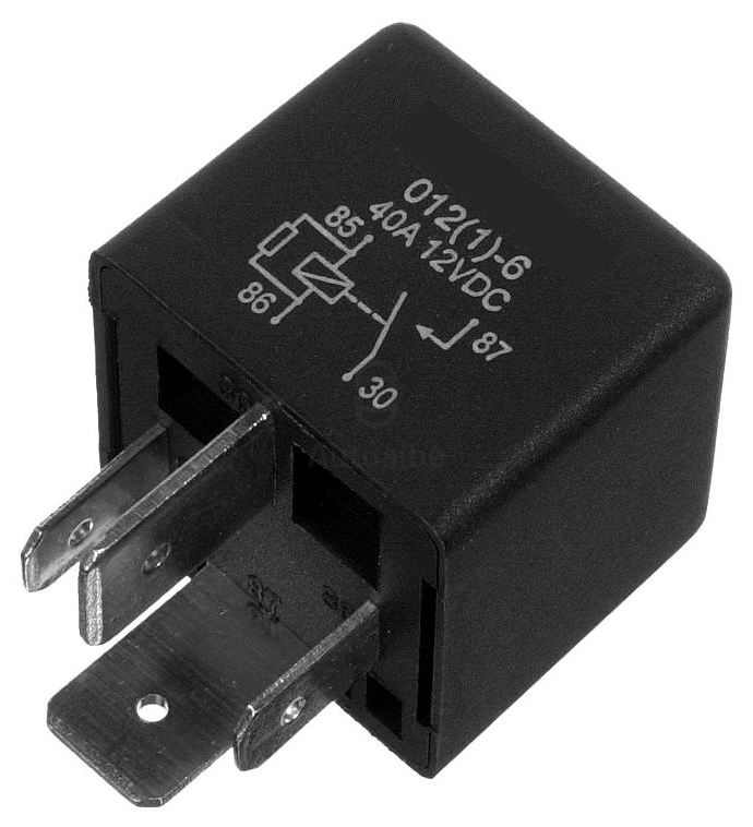
I chose to do free wheel mode with relay option. I use 24v Phidgets motor. Everyone is using 12v relay, do I can to? Or I need 24v relay?
Do I can use this one? It’s basacly the same like bosch 0332019110, just relay pin 85 and 86 is swap places. here is a pic:
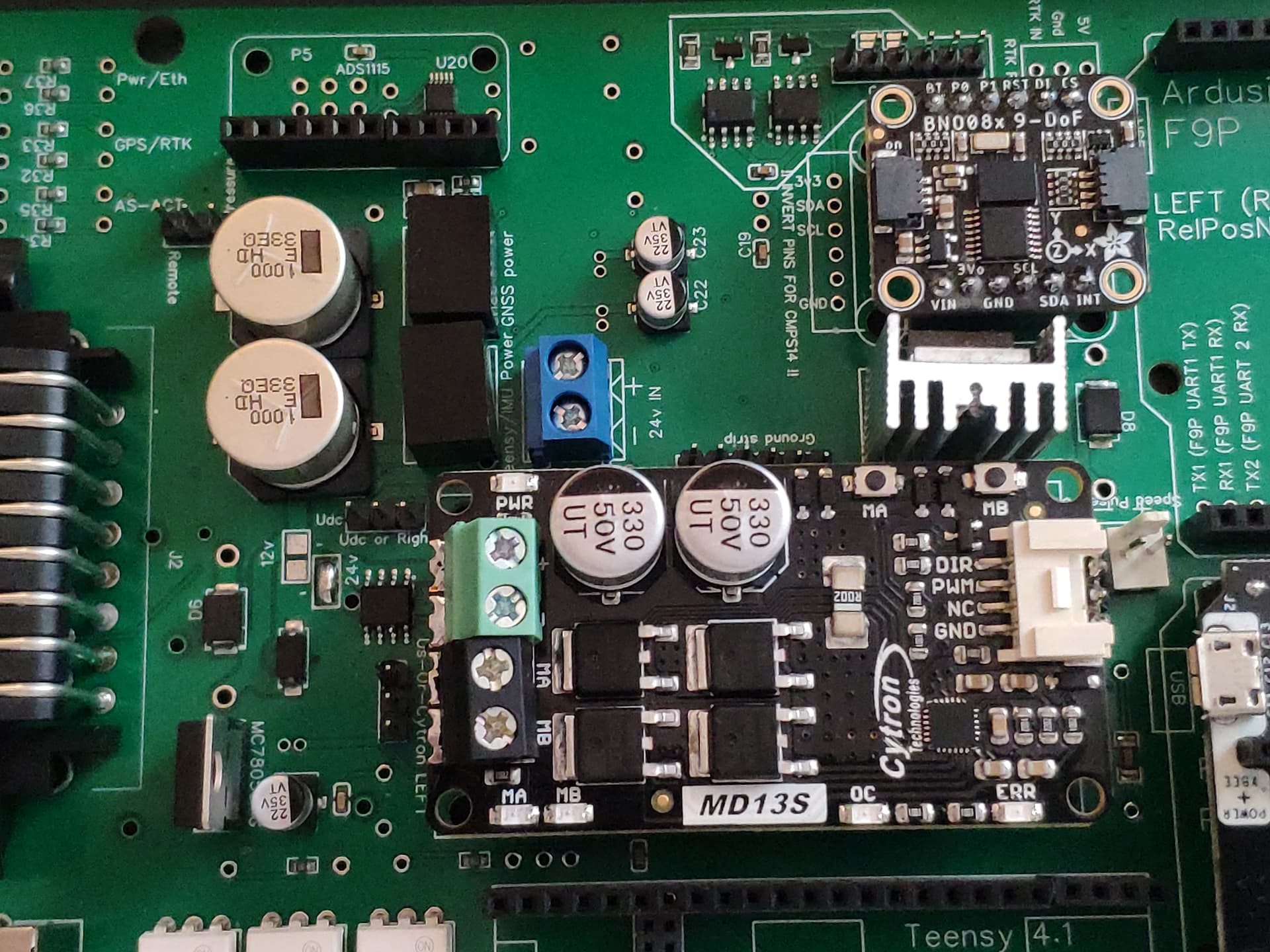
2. Cytron md13s wiring. Do I need to connect something to PWM2 on PCB? And how to conect everthing right? Do I need to 12v to 24v converter wire to the board, or use 12v out from the bord to motor and here concect 24v converter to the motor. Here is some pictures.
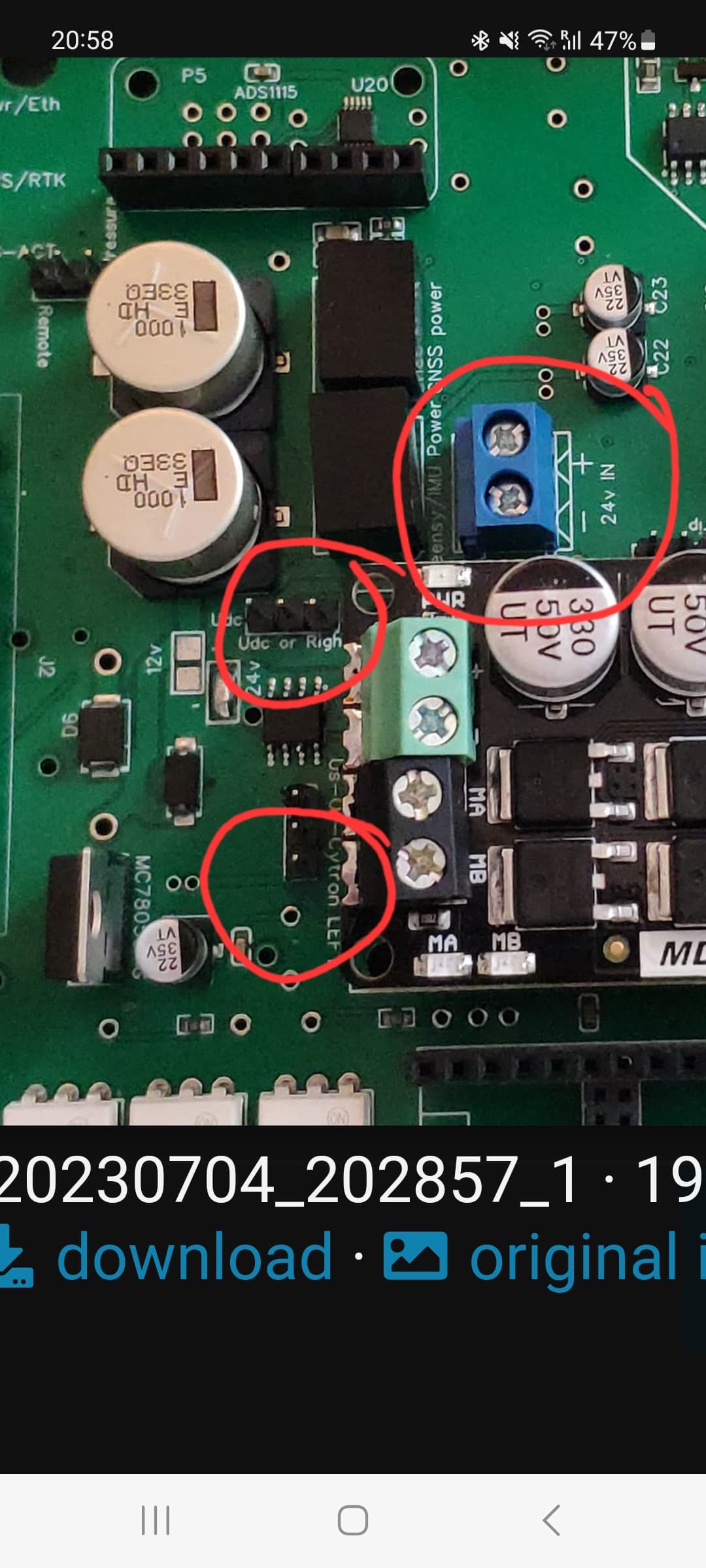
you’ll need some jumpers on both the pins circled infront of the cytron.
The 24v power from your converter is best wired to the 24v in terminals.
You’ll then connect your motor wires directly to the outside of the ampseal.
You wont need anything connected to PWM2
Wont comment on your relay as i used the 12v bosh one listed in the github
Ive added a better picture of the location of the jumpers
1 Like