I see that there is another PCB available, the KaupoiMod v4.
I was just about to order v2 boards when I saw this. Is the v2 outdated now? Should I research this v4 now and order it? I just got confident to try to put a v2 together and now maybe have to do this other
I’m with PCB v2. It’s working great. But I don’t know the difference with Kaupois v4
1 Like
They are both good, I went with pcb v2 because it was well documented and easier to make. Its question when will both boards be obsolete when teensy 4.1 PCBs come out.
Fair enough. V2 it is then. When do you guys think these teensy boards will be coming out in full force? I’ve read even less about them so far.
I use PCB V1 and I think teensy will be in two forms, one for combination with older PCB and one with only Teensy for everything.
There has already been made a HAT to connect teensy to nano board. So I believe more HAT´s will be made.
I am using V2 autosteer boards. I think Kaupoi was working on v3 at the time though.
If buying again right now then I would probably go for the latest Kaupoi. It is a more compact smaller form so should fit in smaller enclosure if needed. It is also designed for the changes in roll and heading sensors. I think most of the different BNO08x boards can be directly connected to it.
If you use V2 then do not buy everything on the parts list. The parts list included two different power relays (Either direct soldered to the board or plug in with a socket soldered to the board) and it still lists the MMA8452Q roll sensor which is no longer supported since software version 5. You can still connect BNO08x boards to the V2 board, but they need some form of jumper wires or resoldering.
Another slight difference is that Kaupoi does list JST and Qwiic connectors as options in place of some of the screw terminals V2 lists. This just comes down to what works best for you. Screws connectors are more versatile, but cost more and trikier to get every thing connected back in the right order again if you need to disconnect things. Wires can even be soldered directly to the board without a connector, though it is not very practical if you need to remove them later, which can happen more often than you might expect.
1 Like
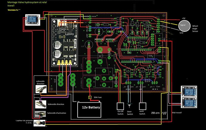
I would like to know if there is any 5v or 12v output on PCB V2 to connect a relay that opens the 6/2 valve only when the autosteer is activated, instead of connecting to the cytron output that opens and closes the valve continuously.
I currently have it hooked up to a switch that I turn on when I get to the field and it stays on all the time.
2 Likes
How is the reverse voltage protection from the 6/2 valve done?
I don’t understand ? why would there be voltage inversion on valve 6*2
You can put a diode across the leads going from relay to valve spool (a 5 v relay activated from pwm2). It should take the reverse current, (induced by the spool on the valve) when relay is turned off again. If you put diode wrong, it will just burn, so put another in correct direction ![]()
Thanks for the quick response, but connecting the relay in this way, the 6/2 valve opens and closes as many times as the cytron moves the wheels to the right and left, that is, it is continuously opening and closing. I have read that the relay burns because of a lot of opening and closing. My question is if somehow the relay could be connected so that when the autosteer button is green there is current in the relay and when it turns red (the autosteer is disconnected) the current in the relay is cut so that the valve closes 6/2. In this way it would open and close very few times. is it correct or am i wrong?
Connecting the relay to PWM2 as in the picture is exactly how you want it to work.
Green = On, Red = Off.
if you fear for the reliability of the relay you can use an mofset assembly such as these:
https://www.amazon.fr/modules-commutation-MOSFET-haute-Power/dp/B092D3YZK3/ref=sr_1_31?adgrpid=1351300727003523&hvadid= 84456759751139&hvbmt=be&hvdev=c&hvlocphy=125609&hvnetw=o&hvqmt=e&hvtargid=kwd-84456822154975%3Aloc-66&hydadcr=2663_2313396&keywords=mosfet+de+power&qid=058-3&1s
anyway pwm2 supplies 5v only when the autoguiding is active independently of the cytron output
Thank you very much for the clarifications, I see I had the wrong idea. I will try this way.
