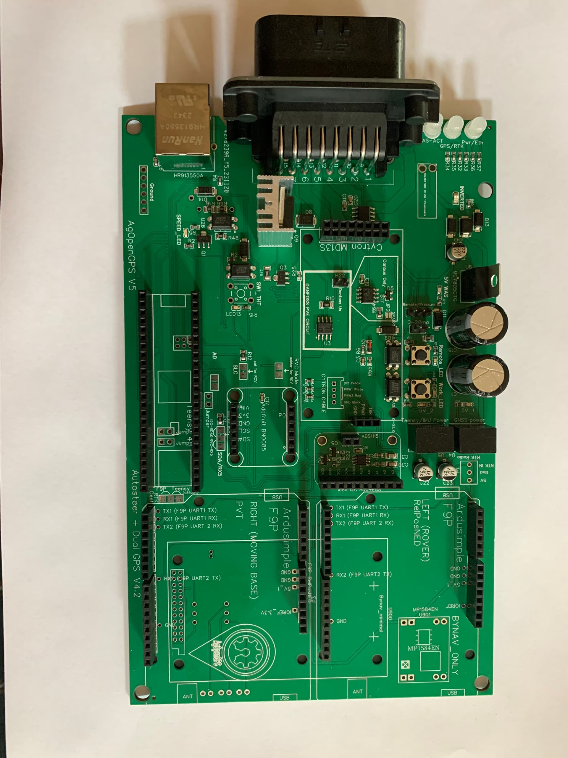
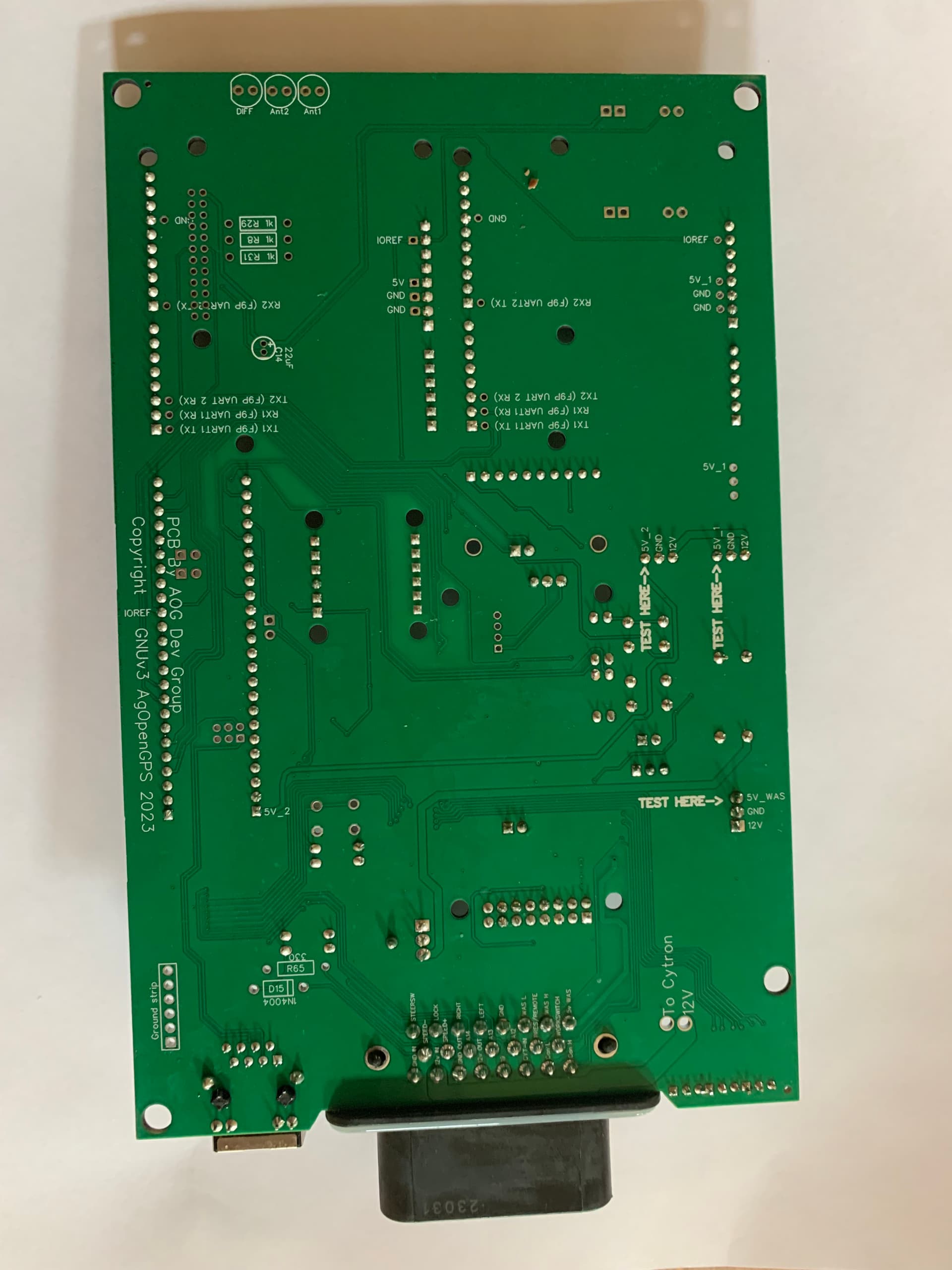
Hello i have a pcb v4.3 part assembled board . I have have made in the past a pcb v2 and have used it for a year or so i was going to add panda but decided to start again with a new all in one board. Ive done some reading as usual have got my self a bit confused . I will post some pictures of the board .
from reading i see that the cytron tracks might need some modification?
I thought it was the same size pcb as the v2 was going to use my old hammond box
If somone had the time for a quick look at the pictures and let me know if i need to do any upgrades to the pcb it would be very kind thanks chris
That is fixed in v4.2 version.
You are missing 2x3 2mm header for teensy ethernet.
Might be a challenge getting some components in too, some of those headers aren’t aligned too well.
Thanks i have some headers here i will solder to the teensy and just plug in i guess its ok to solder the two headers the hole length of teensy both sides .
Andyinv
yes will see how i go with that .
Is the ads115 in the pcb 4.3 board already or do i add like the pcb v2
thanks chris
Radmuffins
Ok thank you i think ive got it now the headers on the inside of teensy.
I am rtk here with base and radios. On this standard board does the radio just stay on top of the fp9 board ?
thanks chris
The ads1115 is already soldierd on your board. Its little chip in the middle with 5 legs coming off it
thank you
Hi
Its been a while finally got my all in one together v4.3
I need to configure it now is there a easy way to go about this ?
I have my own base rtk
so need to configure the teensy and f9p
i also am going to use ethernet connection
I have had a bit of a look but i am getting confused with it all
ntrip rtk to go etc
could any one point me in the right direction
thanks chris
Go there and scroll down to the section on Boards - configuration. Quite a bit of info there.
First do the “Electrical testing and validation” which you pass on the way down to Configuration ![]()
Check out AOG config-o-magic.
1 Like
Thank you i will first do the electrical testing .
then i will try lansalot
knowing me somthing will trip me up
chris
Ok
tested board voltages all good
have flashed f9p and teensy with lansalot seems to have worked .
Now its the tablet
im not sure here i watched a video on this but i think its more for ntrip
I have my own base and this is rover in the all in one pcb and just want to connect via ethernet cable to pcb
i am a bit lost here will do some more reading
i have a pcb v2 ive used for a few years but wanted to try somthing better and use ethernet
chris
1 Like

1 Like
Thank you
chris
hello
not sure if i am in the right place
have had my all in one 4.3 going using version 5.7
its sems to be a improvement way better straight lines
rtk base and rover
have spent a couple of days trying to sort out
just as you think your getting somewhere it trips me up
lots of reading etc
but i kind of think its above my pay level
3 mt linkage seeder 3 pt hitch have delt with offsets etc 150ml spacings needs to be on the mark
so i am at a loss maybe a rtk thing not sure
my question is i start of at the start of the day do the back and forth thing measure its spot on distance between passes
as the day goes on i had to adjust my antenna to minis 9
next day do the same thing its off so set back to minus -1 alls good spot on
is this normal ?
im lost does any one have suggestions
thanks chris
How is your base setup? If it is doing a self survey in at each startup, then it get a new position every time it has been turned off. Could explain shift in ab line from day to day. Change during the day, could be roll/imu problem.
Larsvest
Thanks for your reply
The base has never been moved or turned of since i first started it .
I have not thought of the imu
I will do some more reading about imu problems
Its a improvement on my v2 board but just cant get it sorted
thanks chrs