Take a screen shot before and after and post them here.
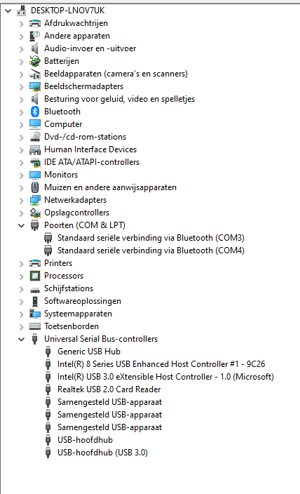
It’s in Dutch unfortunately lol
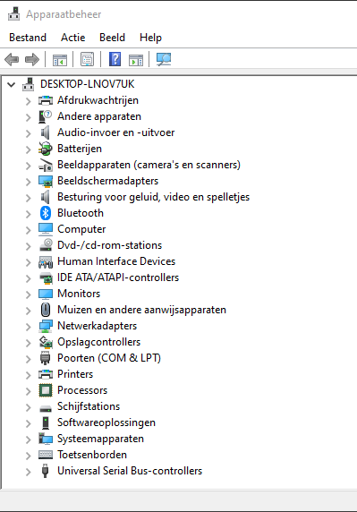
this before:
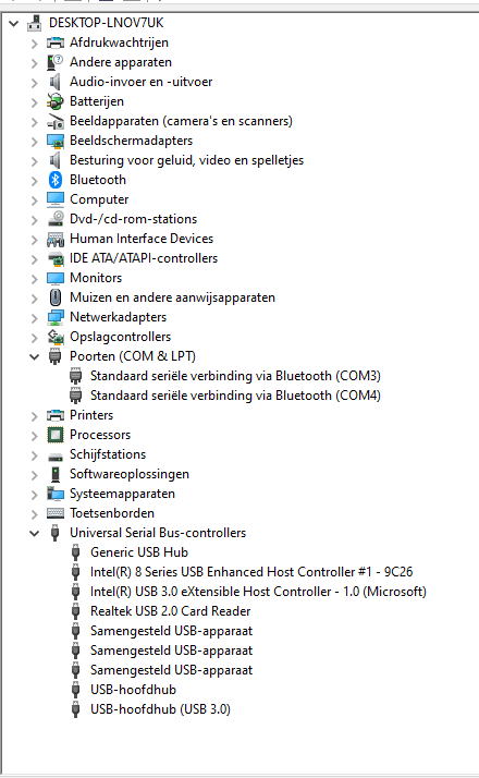
this is after:
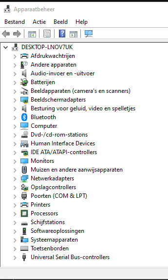
it did do the USB disconnect sound, with a short refresh of the list.
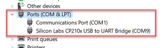
Could you get a screenshot showing the Ports expanded like this?
Once you have you board powered with 12v in. If you cant get a usb connection, try the other micro header. There have been many usb ports that are not soldered well from JLC. I have had to reflow the solder connections on several boards. They have been better as of late, but still not the best soldering.
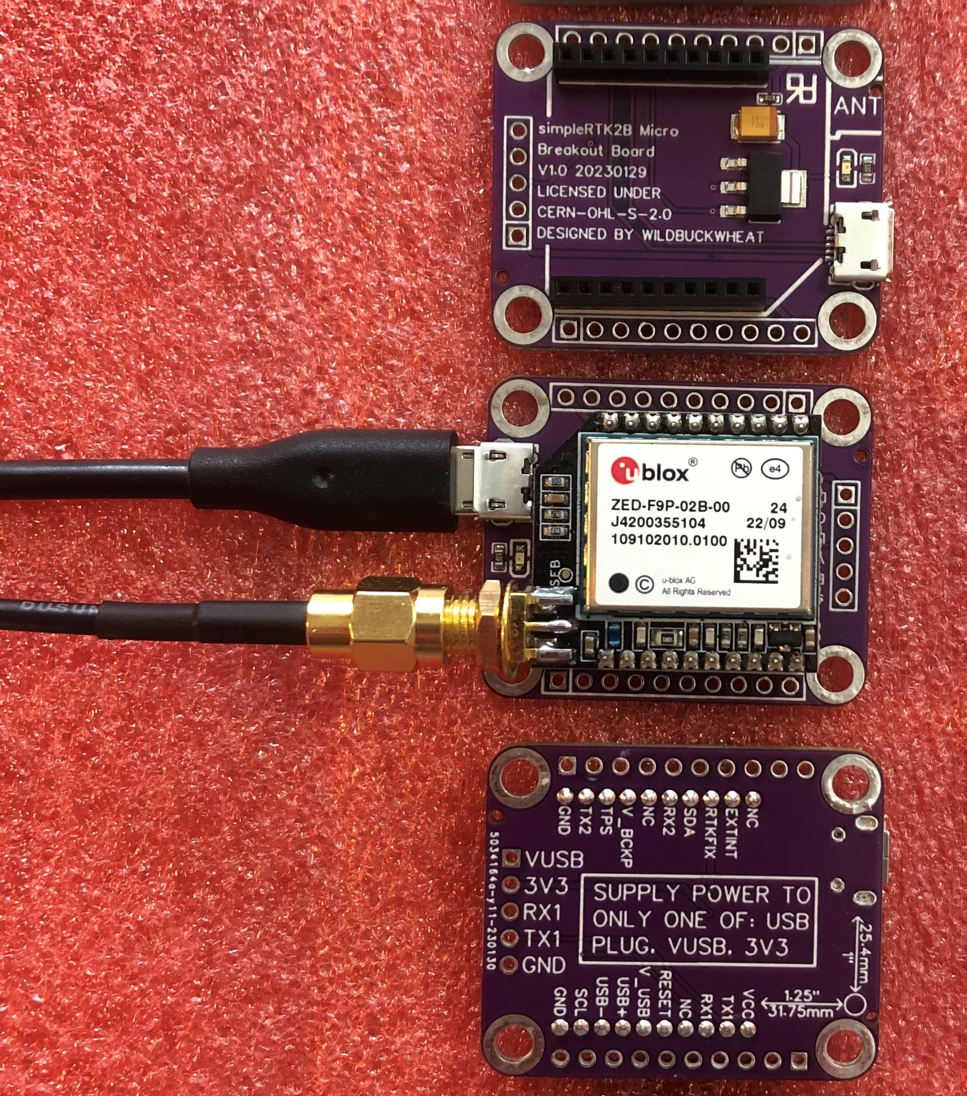
I have started using a micro breakout board designed by @WildBuckwheat
It doesnt need external power but is powered through the usb port just like the standard f9p.
@WildBuckwheat would you please post a picture and link to your micro breakout board?
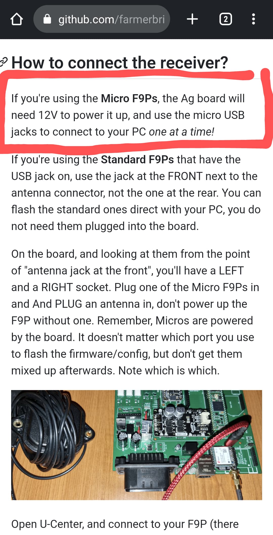
I thought the micro F9P was powered trough the USB aswell. I followed the wiki, the way i interpreted the words “one at a time” is that i never should connect to 12v and USB at the same time, just as you shouldnt do that with the teensy. Also the picture in the wiki shows no 12v in!
Are you sure you can connect the board to 12V and then connect to USB on the micro F9P?
Yea, im sure.
If you don’t power the micro, it will not connect usb.
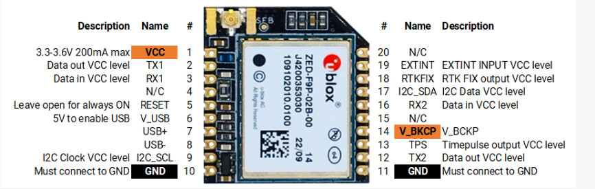
The micro is 3.3v and usb is 5v. Therfore you need 3.3v power to the micro since the usb port is data only with no power to the micro.
Edit
That wiki link is only talking about plugging in to the teensy with board power off. You can cut the trace on the bottom of the teensy and then it doesnt matter if the board is powered or not.
1 Like
Here’s the link GitHub - WildBuckwheat/SimpleRTK2B-Micro-breakout-board: A small break out board for the ArduSimple SimpleRTK2B Micro
Its just a tiny little board that powers the micro F9P from USB (using an onboard voltage regulator). It works great for flashing firmware, and you can use it to make a base station too. You can also use it to stick a micro F9P onto a standard 0.1" pitch breadboard.
1 Like
The “one at a time” refers to only connecting one micro F9P to your computer at a time. You can safely connect both micro F9P’s to your computer at the same time if you want (with 2 USB cords), but then its easy to get confused which is left/right and to upload the wrong settings.
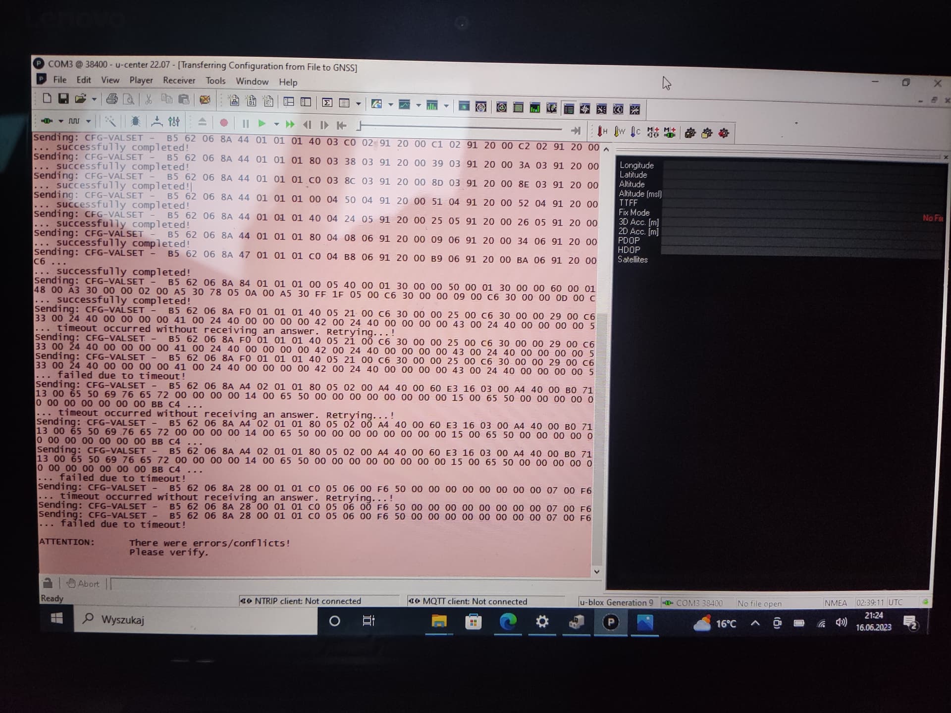
Any idea why i can’t load a configurable file?
I have managed to update firmware with baudrate 38400.

Micro F9p is connected via xbee USB adapter
All problems solved after connecting F9p to AIO board. F…king USB adapter grr
Got it! Finally!
okay so the problem indeed was that i didn’t connect it to the 12v ![]()
after plugging that in, it was just as described in the wiki. Altho the wiki did put me personally off, I probably just misread it (with the warning on the teensy i figured i couldn’t connect the F9P to USB and 12V at the same time)
Thanks everyone for all the suggestions and helping me out!
So perhaps add some info about that in the wiki.
WIKI Tell:
Avoid damaging your computer
NOTE: you should NEVER have your board connected over USB and powered up over 12V at the same time! There is risk of damage to your USB port if you do.
EDIT could be to add this info to the WIKI: “This does not apply to the two USB sockets for the micro F9P´s. Here the 5v supply from USB socket is only to enable USB connection on micro F9P.”
And maybe also add this: “Micro F9P need 3.3V from PCB” (power PCB with 12V)
Print S scr is just for extra info:

4 Likes
Think that will be a good addition to the wiki. I realise im a real novice into AgOpenGPS but having it described like would have saved me personally a lot of headache lol.
Also the picture in the wiki put me off since it didn’t have the 23pin connector in, so i thought i was doing it right.