Hey !
I’m slowly building my first system which will be composed of one PCB V2 + one panda PCB. (goal: autosteer in a deutz M620 and Valtra T120). I want directly to UDP instead of USB for stability.
I’m struggling a bit about the DC/DC regulators and the right way to connect them ( I saw on topics about the panda PCB that a bad pinout might kill the F9P + the Teensy + the BNO ; given the price of electronics I’d prefer to avoid that hahaha).
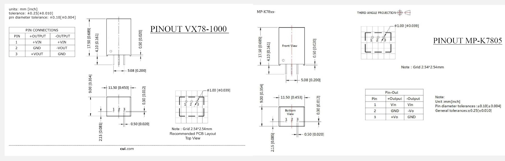
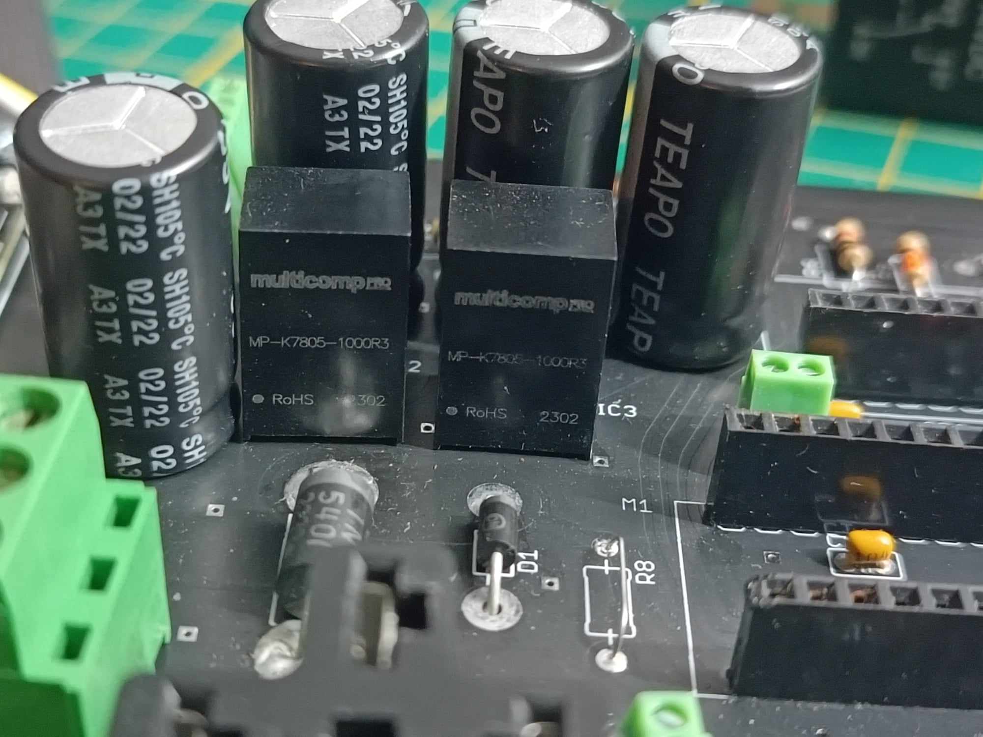
For my PCB V2, the partslist indicated VX7805-1000. As for me, I ordered and used MP-K7805-1000R3 regulators.
Here are the 2 data sheets for both regulators :
Apart from this, can someone indicates me how to check on the multimeter if the connection is right ? I assume that the regulators work like a diode, voltage can go only in one direction, so by checking continuity betwwen the right pins, i should find if it’s good, but I’m lost .
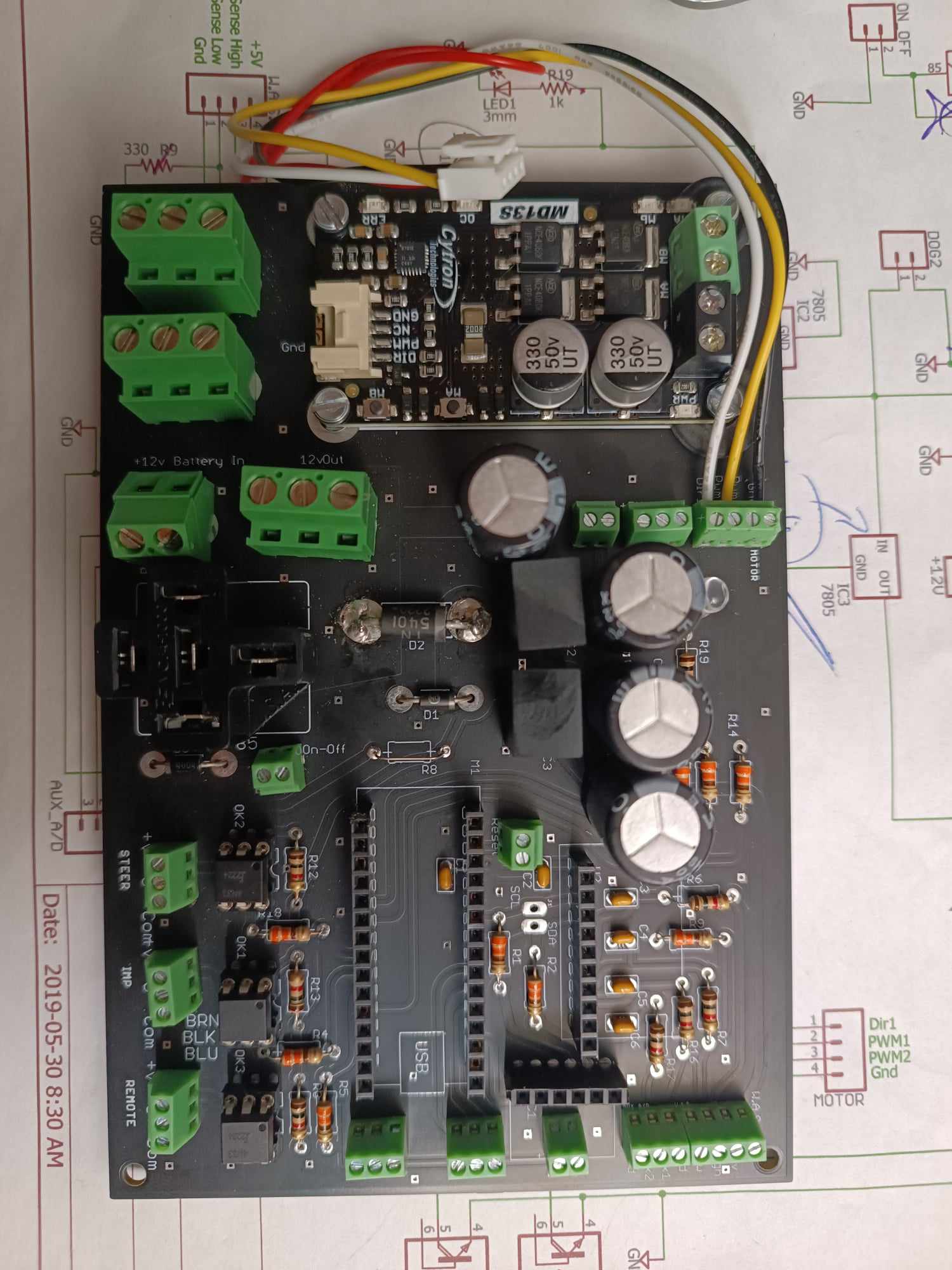
This is the way I soldered it on my PCB V2 :
Thanks for your help in advance! Electronics is not my forte but I’m trying haha
PS : I’m not talking here about the panda PCB, I still haven’t received some parts.
PS2 : Here’s what my PCB looks like right now, I don’t think I made mistakes but can someone confirm me that ?