Rate control how to wire

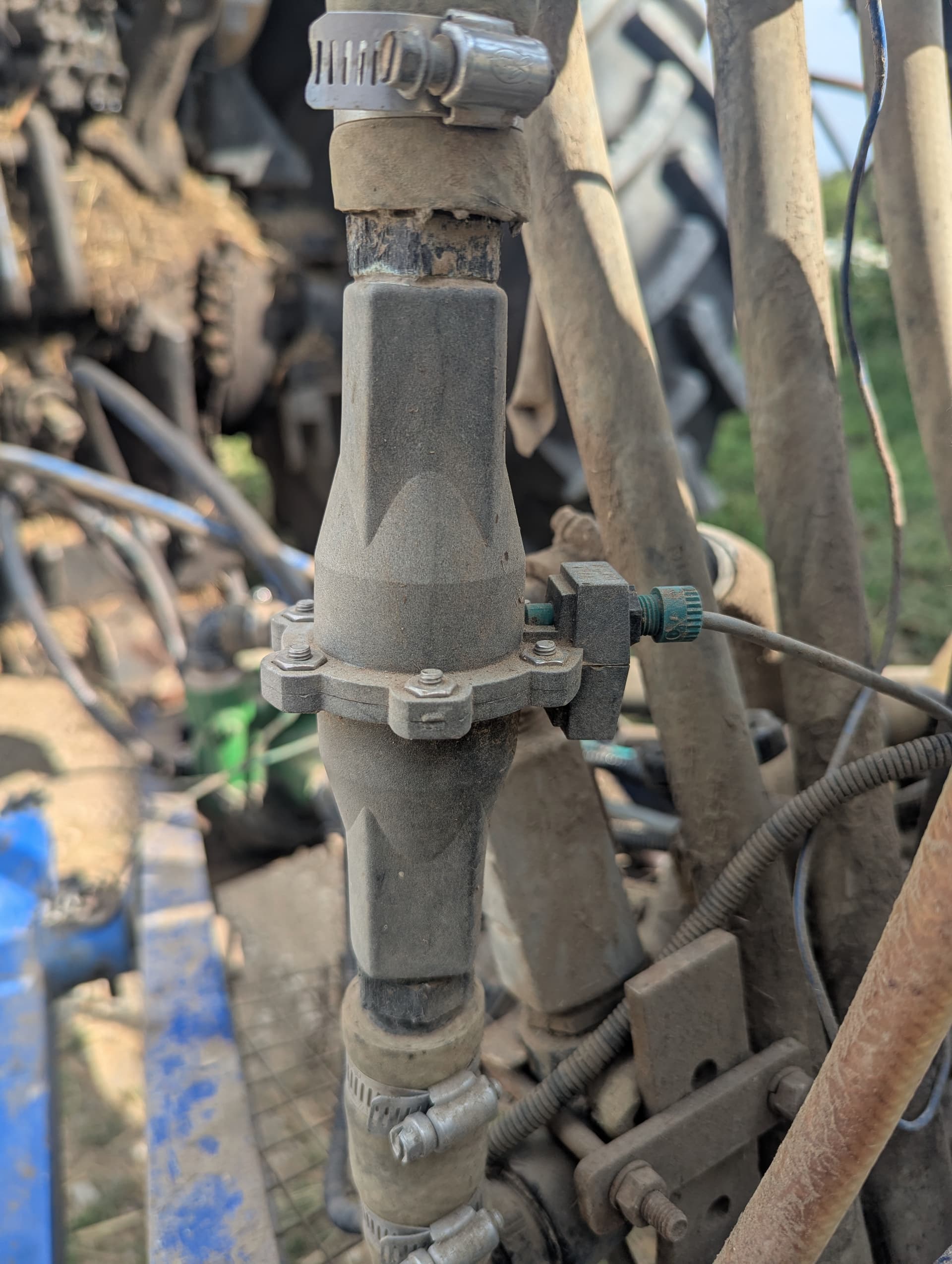
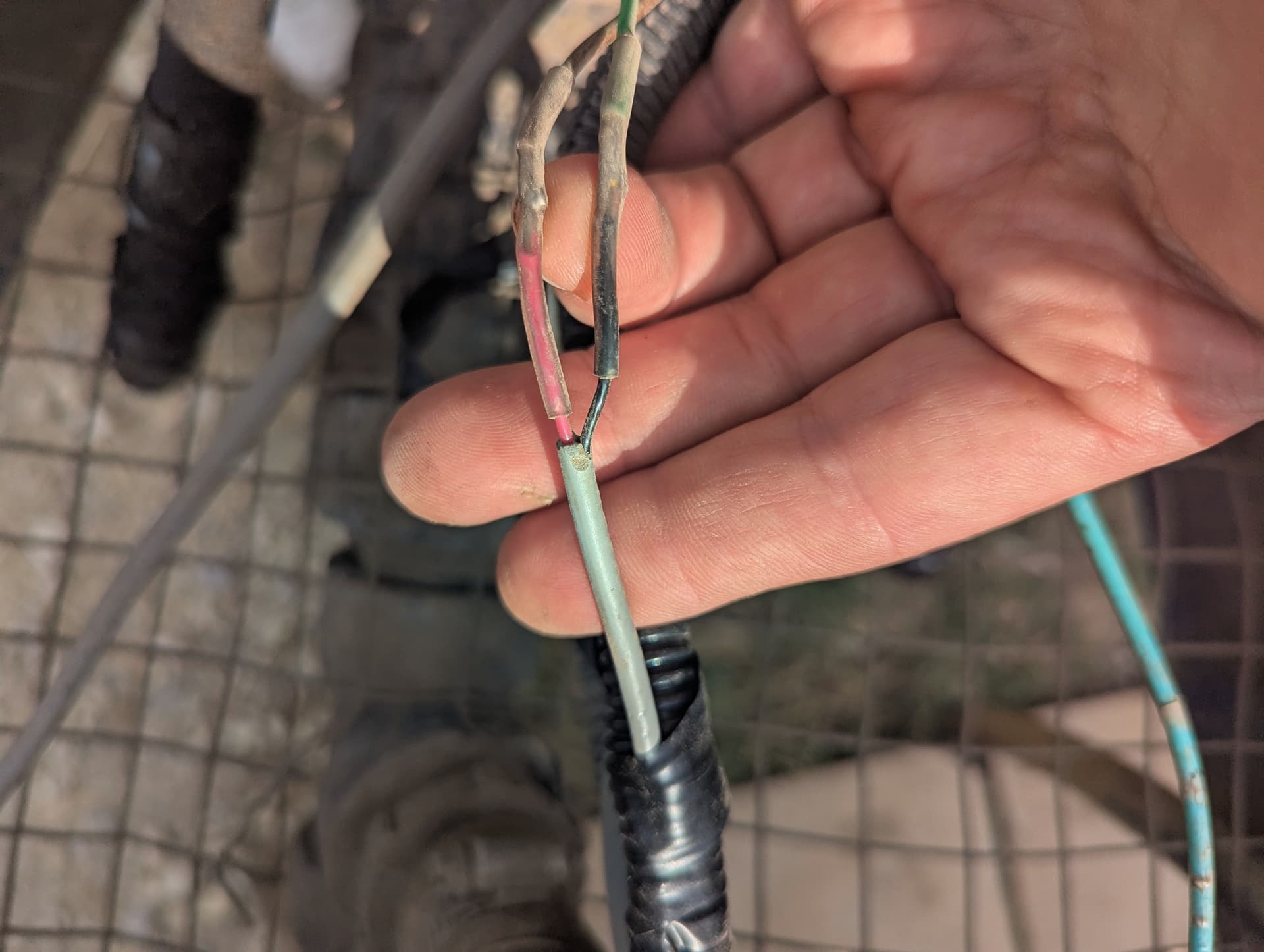
I am setting up a rate control board. I’m ready to hook up the wires and I have questions. I have been unable to find any directions of what the terminals pressure, workswitch, flow 1, flow 2 are to be connected to. My old sprayer has no pressure sensor, it has a sprayer mounted gauge only. What does the workswitch connection do? Is it needed? My flow meter is a Micro Trak FM 750 GFN, and it has 2 wires. How would it be connected to the board?

If there are directions for all this and I missed it, can you give me a link of where it is?

TIA


Rate_Control/Teensy/RC11-2/RC11-2 PinOut.PNG at main · AgOpenGPS-Official/Rate_Control · GitHub The pinout for RC11-2. M1A is flow control motor connection 1. M1B is for the second connection on the flow control motor. R1-R8 are relays to control the sections. Work switch is optional. Pressure is optional. This sensor works: Pressure Transducer Sender Sensor Ceramic Pressure Chip Pressure Transducer for Oil Fuel Air Water 1/8" NPT Thread Stainless Steel Pressure Sensor (100PSI) : Amazon.ca: Industrial & Scientific I also use a FM750 GFN. It has a 3 wire connector. Your 2 wire connector may be signal (Flow1) and ground.

We are using the nano RC 12-3 version

Does the rate controller work better if there is a pressure sensor installed? Or is is just for display of pressure?

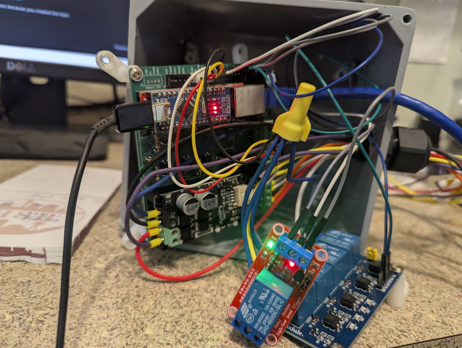
Rate_Control/Nano/RC12-3/RC12-3.jpg at main · AgOpenGPS-Official/Rate_Control · GitHub. Add a MD13S to control the rate motor/valve and a relay module for the section valves: SainSmart 8-Channel Relay Module : Amazon.ca: Automotive

It is mainly just for display. It can prevent over-pressure if set up that way.

I have that all done already, just had questions how to hook up the wires. Thanks for all the information you’ve sent.

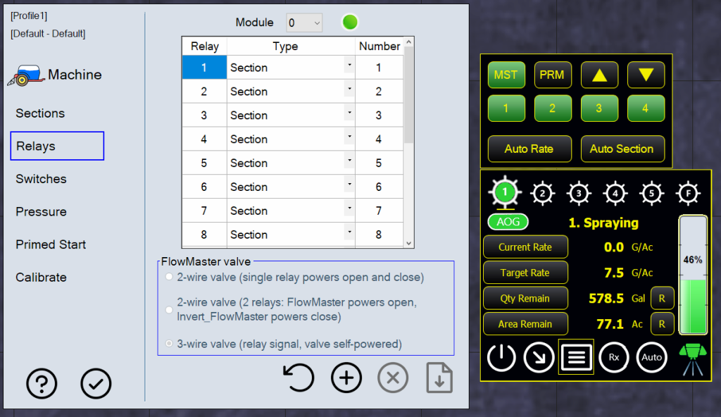
So how do we test the rate control? We have it connected on a computer and have the simulator on and drive and it does not click the relays when it shows on the simulator that it is spraying. Are we testing it wrong?

The section control relays stay on even when the software (AgOpengps and RC) are shut down. Any ideas what to check? We weren’t sure if the 4 relay board is working so plugged in a single relay board as shown.

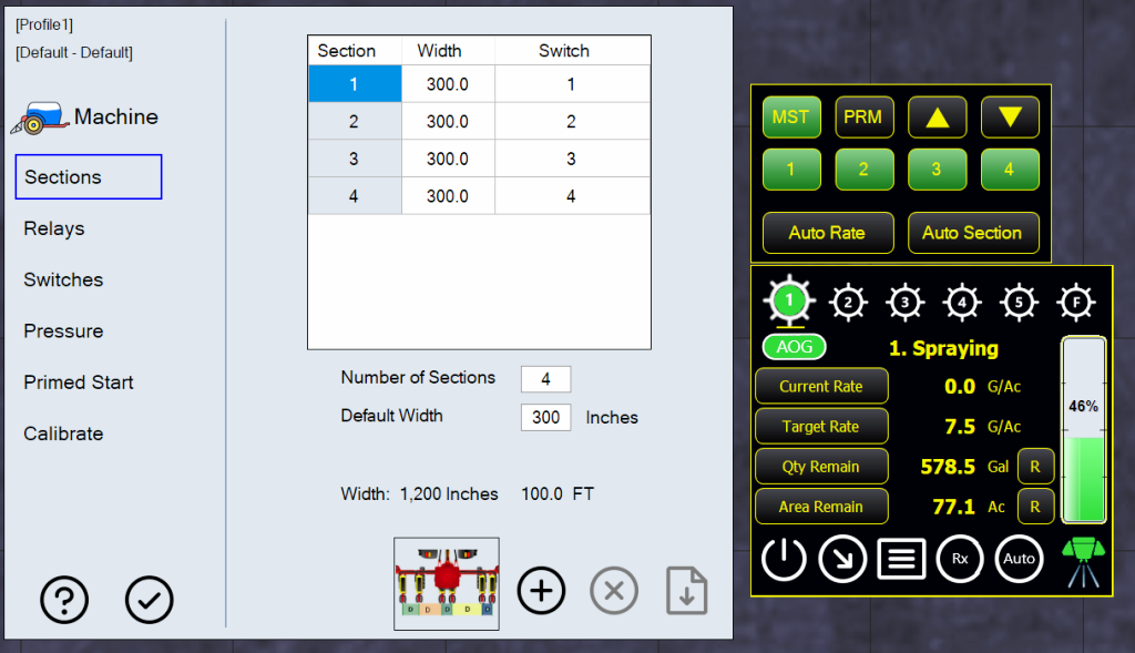
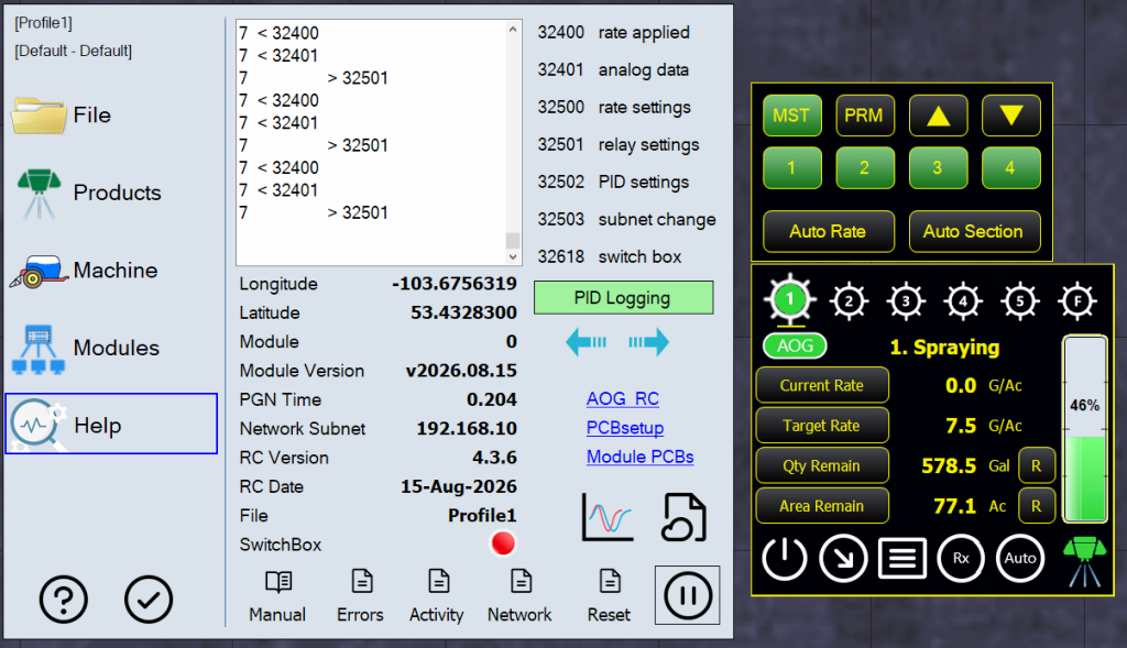
You can test the relays by using the on-screen switches in manual. Are the sections and relays setup correctly? Is the app communicating with the module. Green 1? PGN Time about 0.200? PGNs flowing back and forth?