Howdy from the Midwest.
I have been doing some reading trying to figure out what I need to order for the rate control portion.
What would be the best RC PCB to use? I already have a separate relay board, cytron MD13S, voltage converter, nano, nano shield.
Do I understand correctly that I need 2 separate nanos? one for rate and one for section control.
The smaller the PCB is the better, as my goal is to put this in the 440 case.
Auto steer setup is V2 board, f9p ardusimple running with nano shields to ethernet switch.
The smallest and least expensive is the RC12-2. It is all through-hole parts so it needs to be hand soldered. It can do rate control and section control using another small board mounted on a 8 or 16 sections relay module. Here is an overview of the boards: GitHub - AgHardware/Rate_Control
@SK21
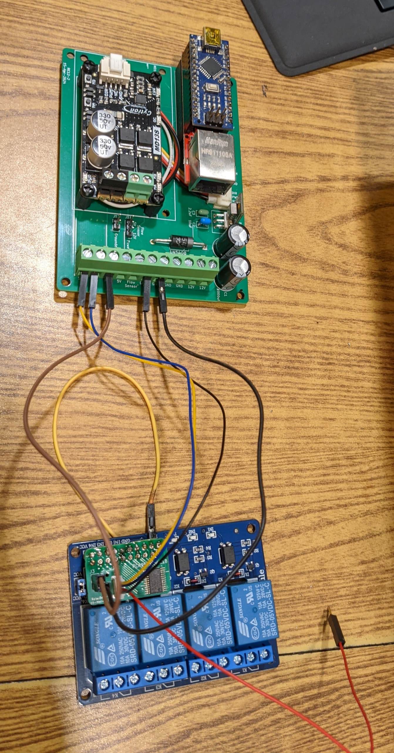
I have a few questions to clarify that I’m hooking the RelayDriver5 and RC12-2 up correctly.
What pins on the relay driver 5 correspond with sections 1-4? I have a 4 relay module.
Does the red wire (3.3v) not get used from the Qwiic connector?
I’m thinking that the 2 wires from the flow control valve go to MA/MB
Some what unsure of the 3 wires from the flow meter, I need to finish reading through this thread raven-flow-meter-connection-problems I’m hoping that will shed some clarity on how to hook it up.
I’m sure I will come up with more questions in the coming days, Thank for your insights.
It needs to be a 8 or 16 section relay module. The connector on relay driver 5 won’t line up with a 4 relay module. The red wire can be 3.3V or 5V on the relay driver 5. For the RC12-2 pcb it is 5V. MA/MB control the flow valve.
The flow meter should have ground, power and signal. If the signal is providing 5V or 12V there is a jumper to set for that. If the signal goes to ground there is a different jumper for that.
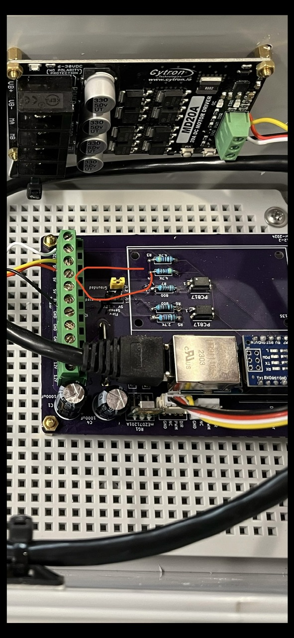
If you are running a flow meter compatable with a raven 440, you will need to put a jumper on the two pins that say “Grounded” (circled in the picture) On the screw terminal block, you will need to connect the signal wire to the port labeled “flow sensor” The Raven flow meter runs on 5v, so connect the power and ground wires to the flow meter to the one of the 5v ports and one for the ground ports on the screw terminal
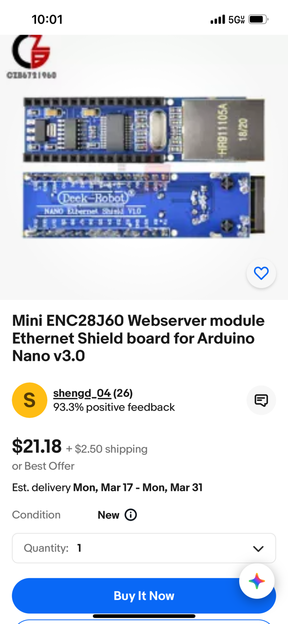
One thing to mention, I had flash backs after seeing the picture of your set up, the first RC-12 board I put together I went round and round with, I could not get it to connect over UDP. I bought a pack of red ENC28J60 Ethernet shields like the one you have. I tried all 3, but it never worked. I could plug into the USB on the Nano and connect over a com port, but not over Ethernet. I eventually bought one of these blue “Deek Robot” brand shields off of eBay, then when I tried it, it worked right away. Just something to be aware of if you run into issues.
I bought a pack of 5 of them last year, a neighbor and I split them to use for updating our autosteer boards to UDP, it took us awhile to get it all working but it they worked last season…knock on wood…
Which RC board should I use for controlling a PWM hydraulic motor on a planter? Currently uses a Raven 662 for planter control and raven components (pwm valve and speed sensor)
I’m making more progress but I have hit a roadblock…
When running simulator with no load (motor valve) hooked up to the relays all works as it should.
When I have a load hooked up to the relays, most of the time AOG will turn the section on with no issues, but every time it shuts section #1 off ( that’s the only one I have a load on bench testing) it shuts all 3 relays off and the only way to get it to work again is to close the rate app and reopen.
I did switch it to section #2 and the same thing happened, also tried a simple 12v motor and the same thing happens.
Any Ideas would be much appreciated, here are a couple of pictures of the setup.
I was able to make the 4 relay board work by soldering jumper wires for the ground and 5v that allowed me to move the 4 signal pins to where needed. (got it right on the first try)
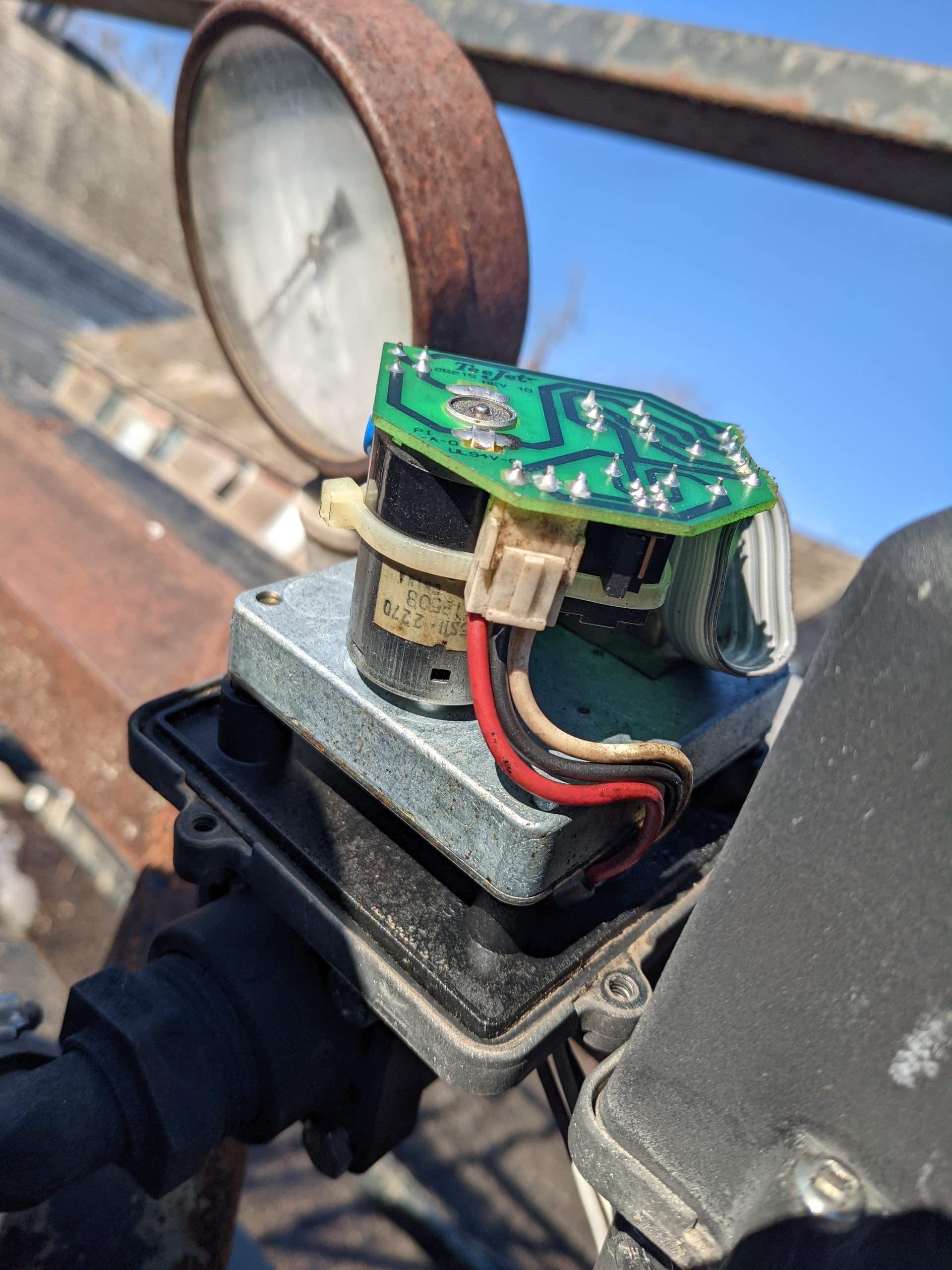
My boom section valves are Tee-Jet and they work a little different that what I have seen talked about on here. They use a 3 wire but I only need one relay to open and close each section.
I labeled the second picture below to help give clarity on how it is wired.
Also threw in a picture of it on the sprayer with the cap removed. (red = constant 12v & black = ground & white = trigger/signal to open valve when 12v is applied)