Hi,
I have just had my RC11-2 boards arrive from JLCPCB. I used all the supplied files on github and while I had to rotate all the header banks for the teensy to align (they were all 90° out), and the grove connector for cytron is wrong, theyre looking good I think.
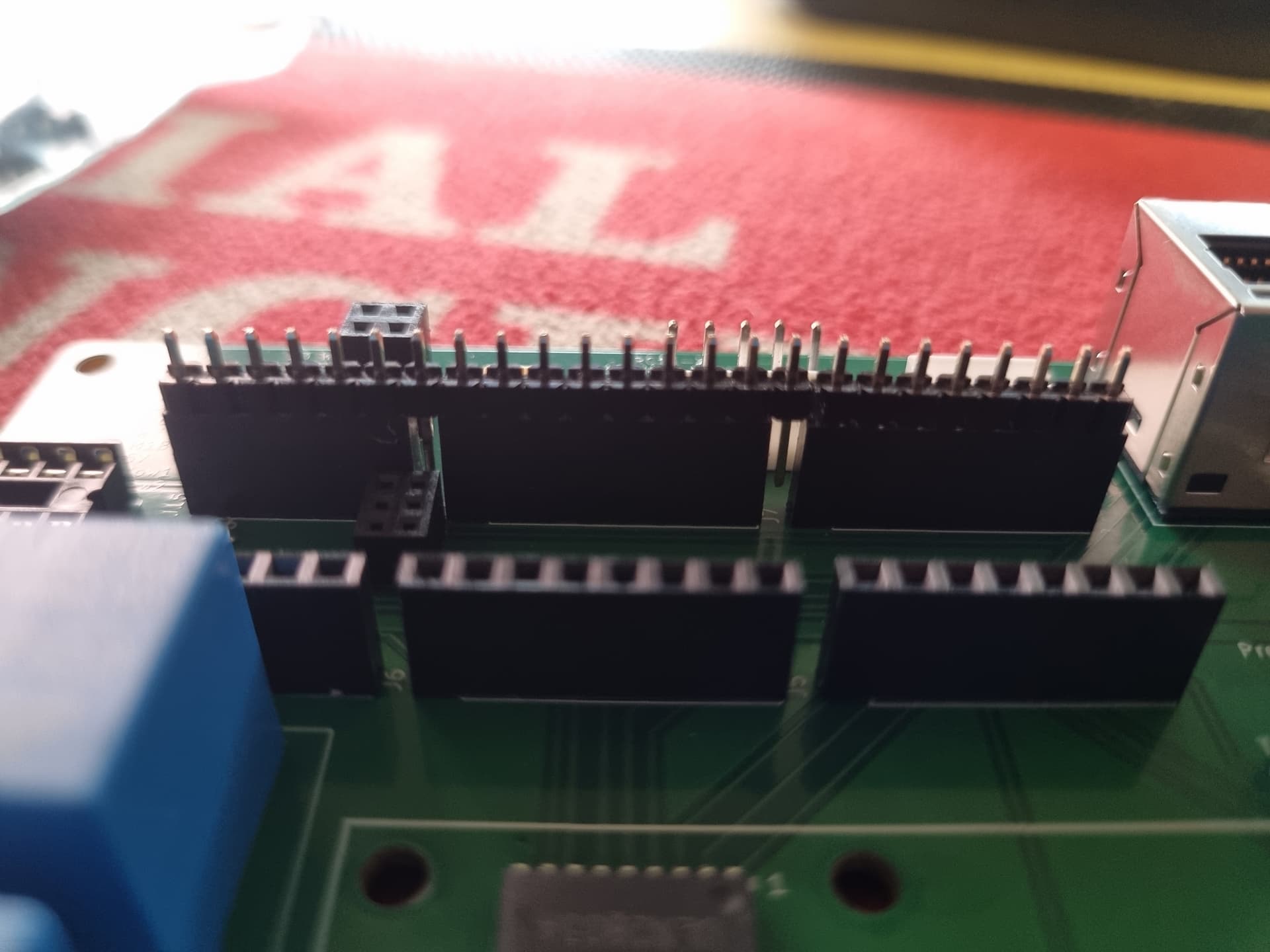
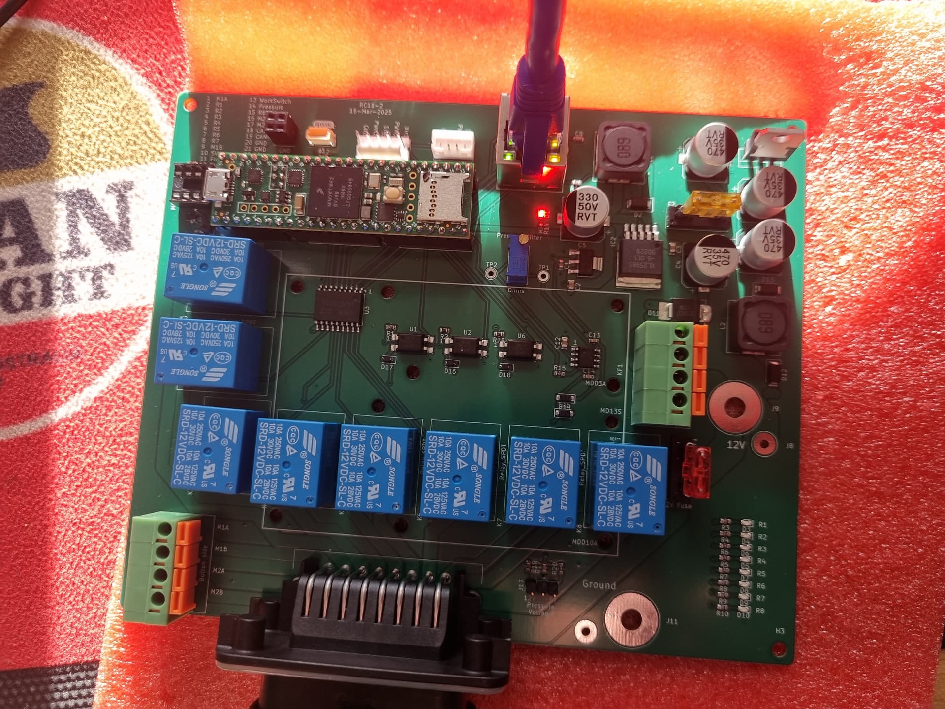
I am in the process of testing my first one before going to the effort of doing any wiring, and my question is about the Teensy header locations. The way the banks are laid out there is 2 pins on each side that arent plugged in. Is this normal? Is it ok?
Attached is a photo of the gaps.
If anyone has any tips or wisdoms for someone embarking on their first RC board set up and use, feel free to help out! My inital plans is to use it just for section control to replace my Rinex section control system, and then later let it replace my TeeJet 844 controller.
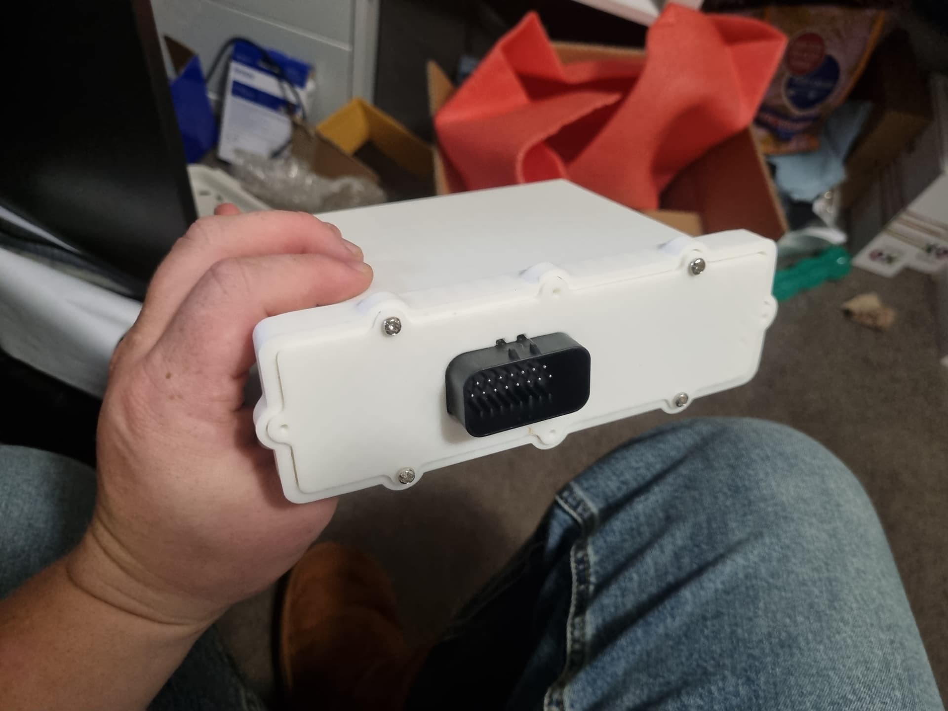
First test of the RC11 housing printed in PLA on my Ender 3, I think I will outsource that job to JLC and let them resin print it at about $100 a throw…
Thanks, thought best to confirm before pressing on.
My next questions!
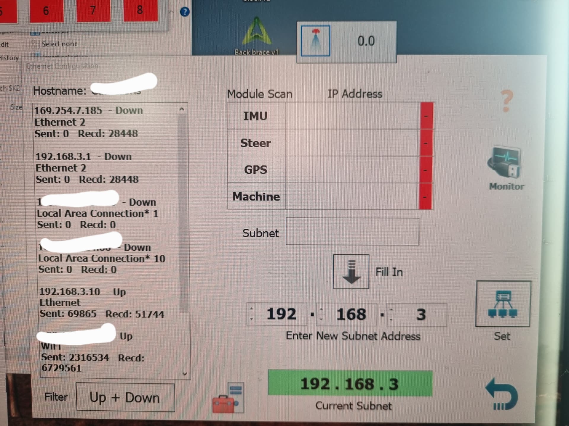
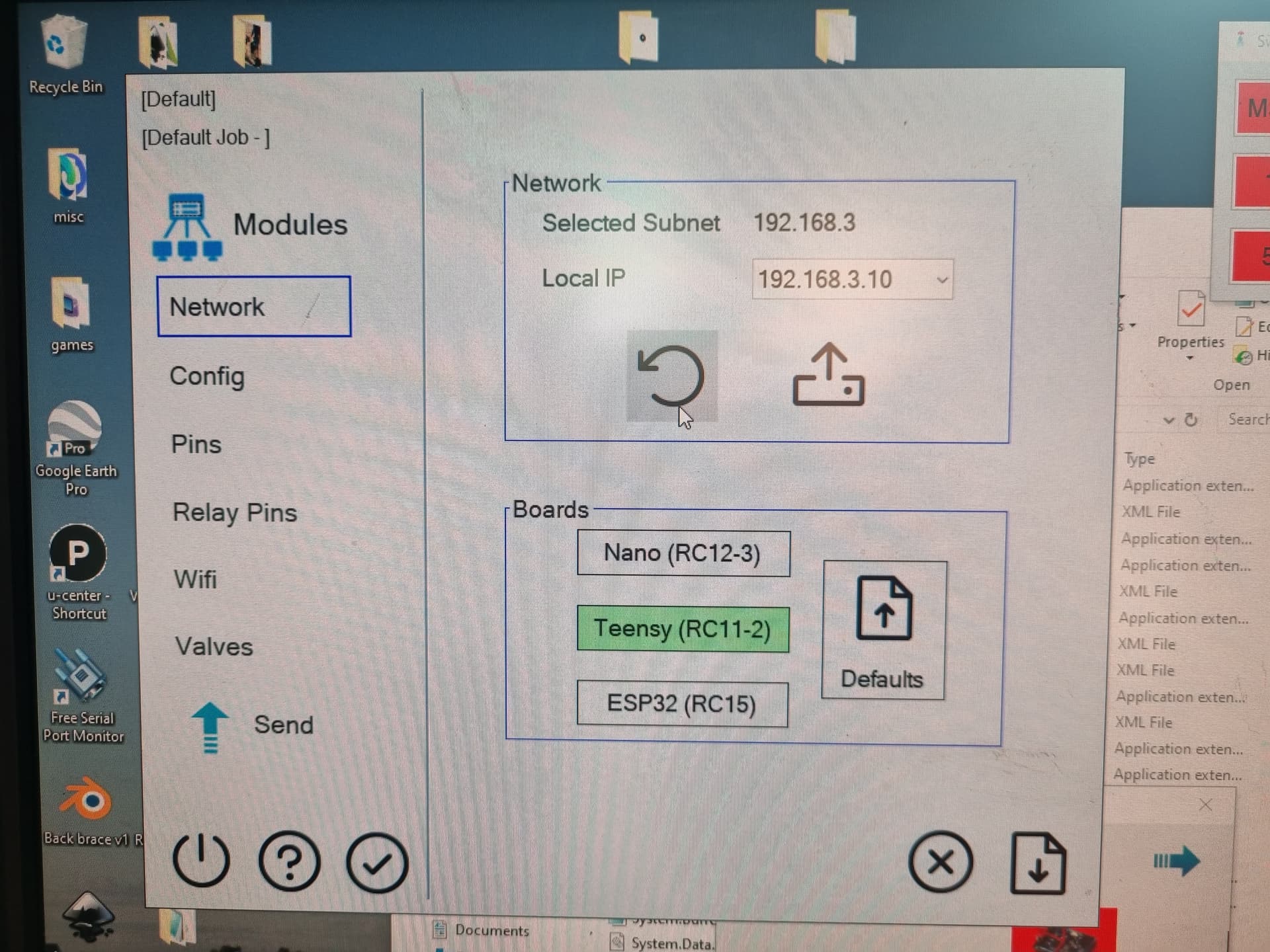
I have flashed my teensy, and plugged my ethernet in to a cable I know works, as it worked with my v4.5 board minute’s before, how can I make sure my board is actually connected? Will it show up in AgIO?
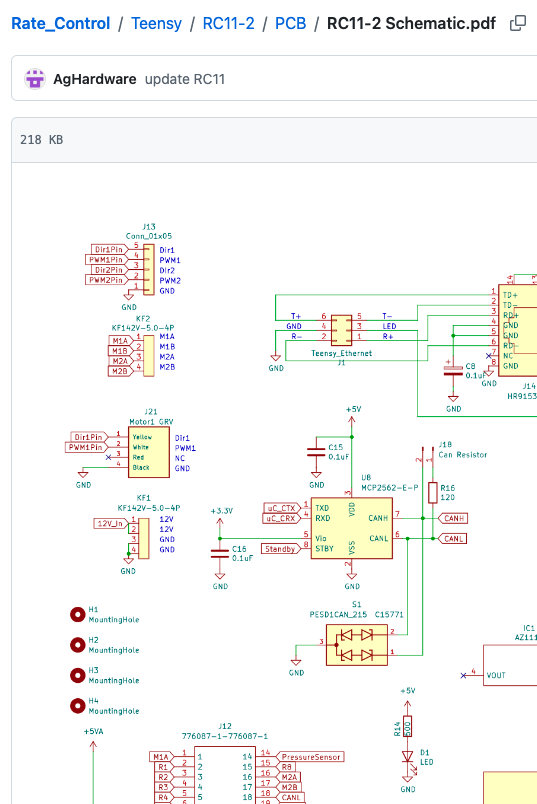
I also have the D1 LED under the ethernet port solidly illuminated, is this an indicator of power or an error of some kind? I also seem to be missing a chip “MCP2562-E-P” is that required for just section control?