Got my boards turns out one of the missing parts was the usb micro plug. OOOOHH NNNNO. Anyways I soldered onto the CH340 directly. The on board led lights, but the comm isn’t recognized on the PC. Is there an enable pin that needs to be pulled on the esp or does the ch340 do that?
Is the usb cable your using definitely power and data cable? Some are power only which might explain why your getting some lights on
He obviously has 4 wires, I don’t think its power only…
I know when using arduino as ISP to put code on other chips RESET pin also has to be wired, maybe thats whats missing.
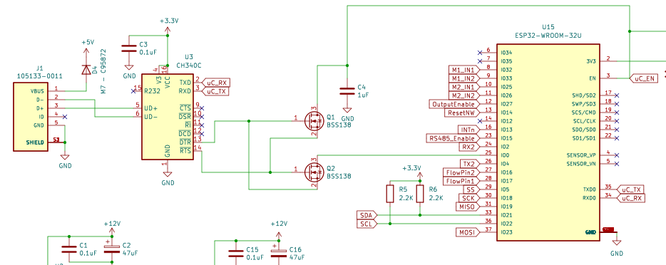
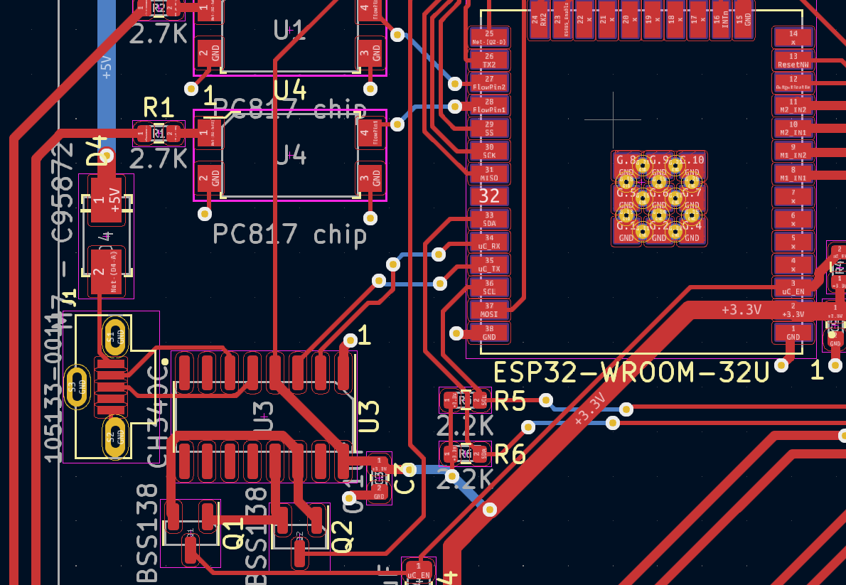
GPIO 0 of esp32 must be at gnd during flash.
EN must then be used to reboot.
Got it. Don’t have to have Data + & - at the right place. “But it helpth”
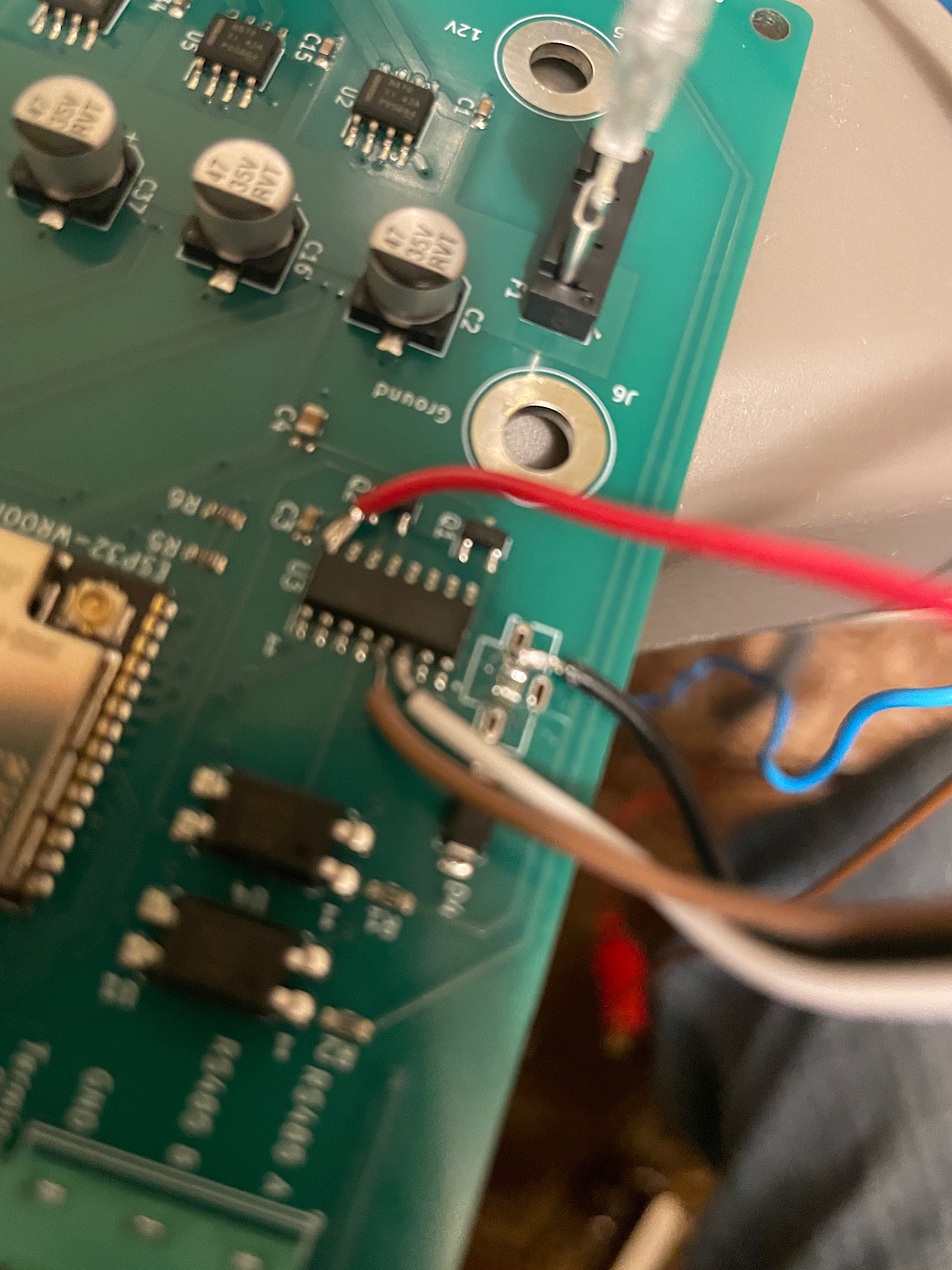
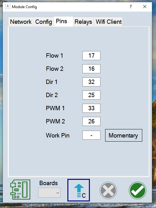
Ok this app is loaded. Trying to run a sprayer. I have my flow meter hooked up to the board. Black to ground, white to 5v and red to flow1. I am not seeing any response on the bench. Any ideas?
There was four wires and four pins in the end bit probing it with multi meter seemed like they didn’t go through. So that was definitely part of the problem.
Module config values sent to board from app?
On the menu select ‘Modules’.
If the module is not connected (Mod is red or blue) the subnet must be set. On a first time install the ESP32 will provide a hot spot to connect to. On the PC connect to the network starting with ‘RateModule ( mac)’. On the modules dialog refresh the networks and select the hotspot. It should begin with 192.168.200. Save the edit. Mod should now be green.
If the module is connected (Mod is green), select RC15 under Boards. This will send the correct pins. Save edit. Upload to module with up arrow.
Using the large screen mode, instead of Mod the P1 icon is the indicator.
so if I unplug the board and the P1 turns red means my board is connected to the app right?
Wondering if I can simulate a flow meter by tapping pin 10 to 5v or grind pin?
P1 is green when connected. Tapping might work.
I sent the settings and it says settings sent.
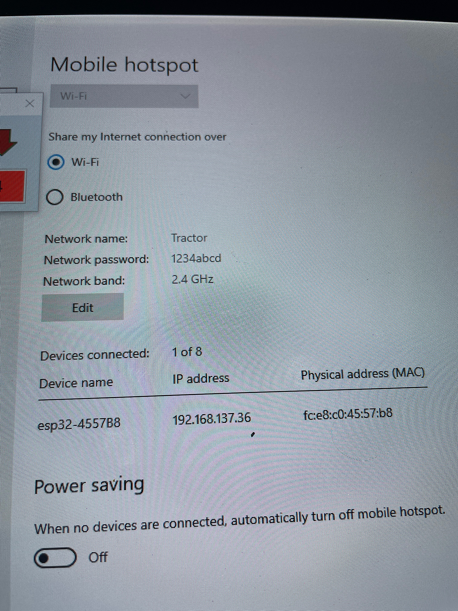
So this doesn’t mean I’m connected? (Made a hotspot on my comp “Tractor” “111222333”
Ok if using a pc hotspot the esp is connected but the app doesn’t know on which network. On the Modules/Network dialog select that network and save the edit.
One step closer. Got a green P1. ![]()
![]()
![]()
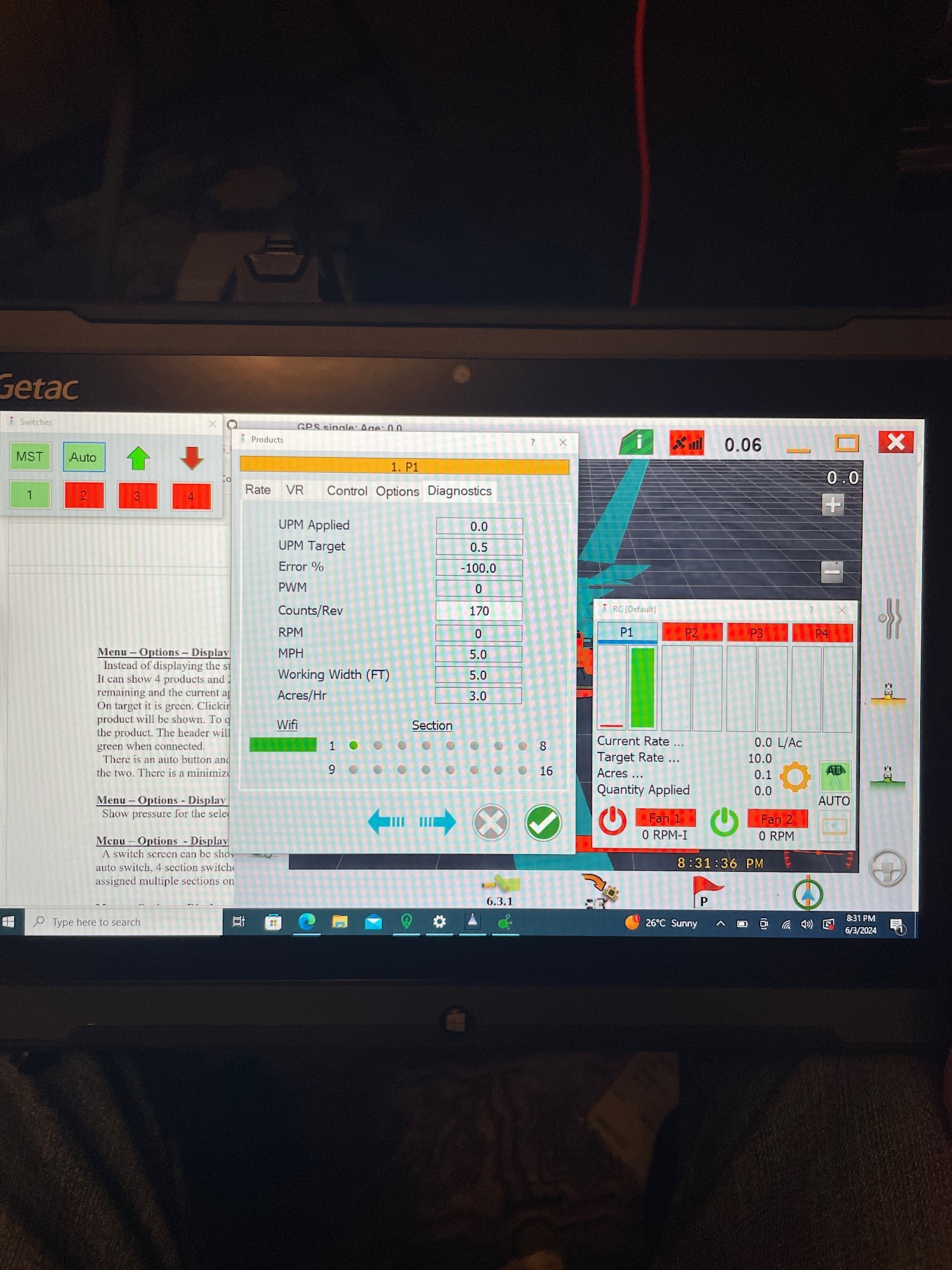
At one point I got 12v out of section 1 but still haven’t seen any reaction on flow meter input. May have to try manually to see if the flow meter is bad or if it’s a setting somewhere.
So if I touch the flow leads off the board together the monitor starts showing.
Diagnosing my flow meter…
Do I understand the flow meter right? I’m thinking it is a simple Hall effect. 5v down 1 wire, ground and if held by metal it should read a voltage on the sig wire is that correct?
Hall effect uses a magnet to trigger the sensor, induction coils use a piece of metal moving past the coil
1 Like