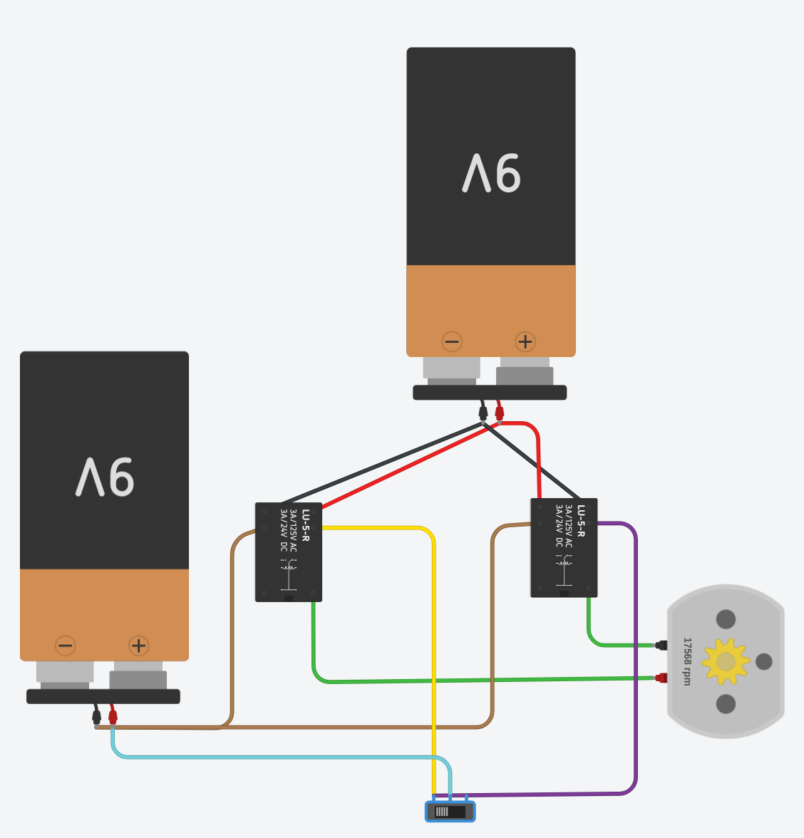
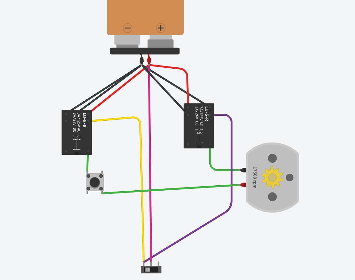
Take your first diagram and put the purple wire at the same place as the yellow on your switch.
Invert black and red on one the relay.
The switch simulates the section control output from the board (power, no power)
With the switch to the left, the motor runs one way (to open the seeder and seed). With the switch on the switch on the middle, the motors runs the other way (to close the seeder)
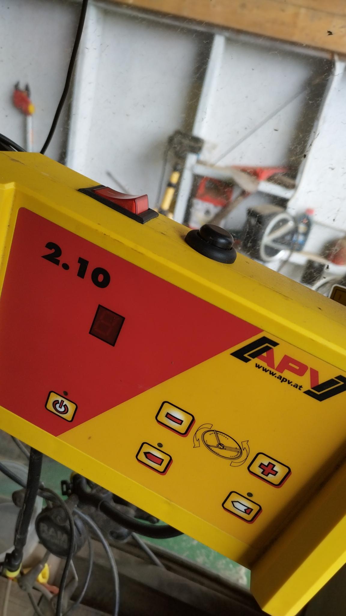
Do you have an operator manual for this controler ?
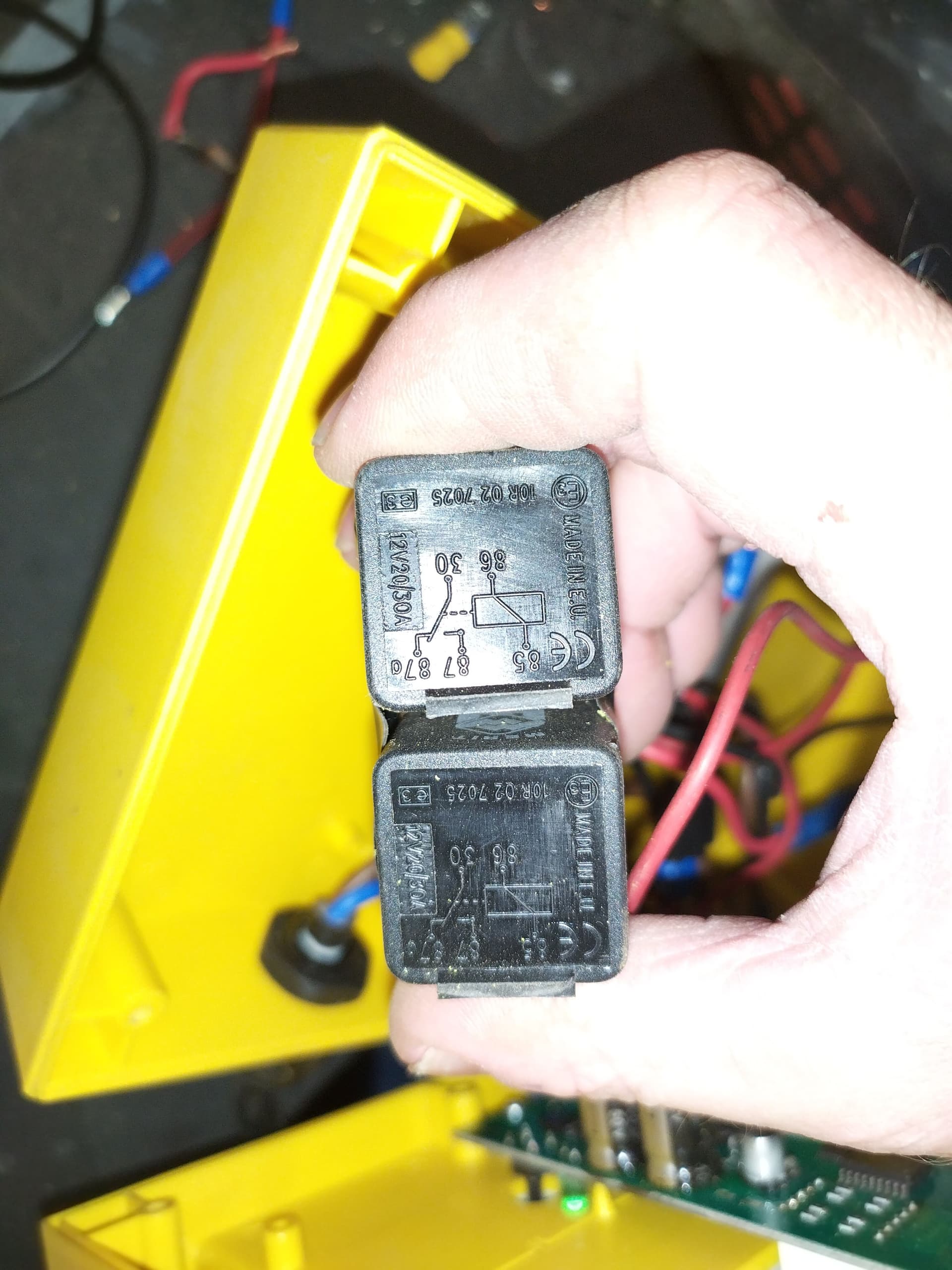
So, it has to be 2 relays in addition to the the section board relay.
Think I got this now. Thanks a lot.
Yeah, but nothing fancy in there. Just a simple users manual.
But there’s (lets say) button [A] to open and button [B] to close.
So I guess another possibility would be to let the relays short the circuit to the respective buttons…
I actually thought of this for lowering/rising the 3pt hitch too.
Originally the open/close buttons also activate a timed relay that cuts power after the actuator is engaged.
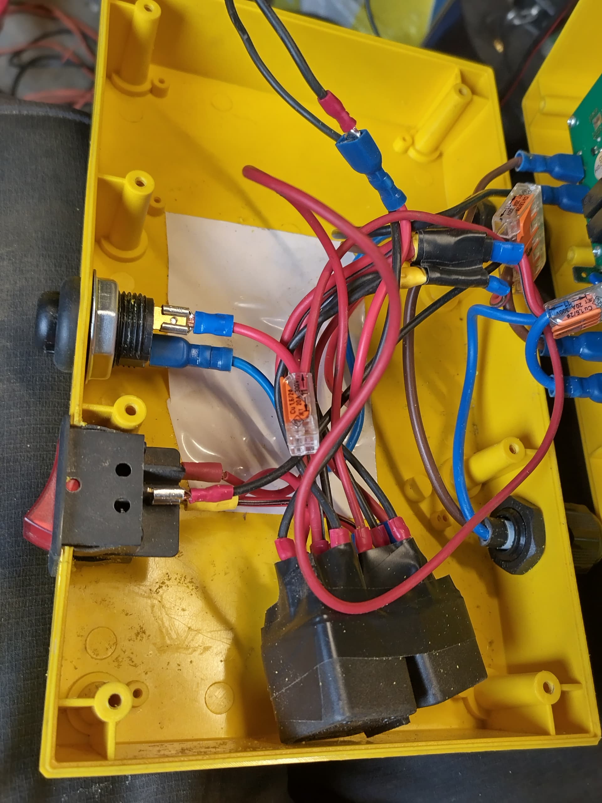
I added a switch on top of the control box to manually open/close, and a pushbutton to close the circut. This was actually quite a userfriendly mod itself.
Got a timerelay today to automate the cutoff. Then i should be able to use it with the section control
Just try connect them as the working sketch from Tinkercad above.
Strongly advice to use a 12v supply and test with multimeter til you get the basics.
Then you can’t break anything.
The relays will have 2 cables outputing the power to the actuator. I made one of these wires go in and out of black pushbutton.
Then, when I release the button, the power to the actuator is cut
Swap polarity with the switch, and “send the power” when the black button is down.
Hi,@guimchevalier.
Do you happen to know where to put a timer relay in this circiut?
I need to cut the power after the actuator as been activated, before I put this on the section control board.
The pushbutton now works as a manual cutoff switch.
If I understand correctly, you need to control the motor gate x second, just enough time for the motor to move to the new position
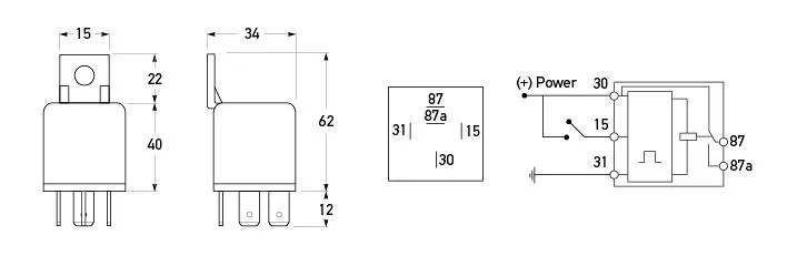
To make this happened via relay, I would put the contact of the timer relay cuttig positive from battery to the two SPDT (but not to the switch). The coil of this timer relay need to be connected on the two position switch. You will need two relay (1 timer for opening and one for closing) on each position on the switch.
I would prefer to make the timer on the arduino and use only 1 standard SPDT to give power during a few seconds for these two SPDT when a change was required. It seems more flexible for me and easier cabling.