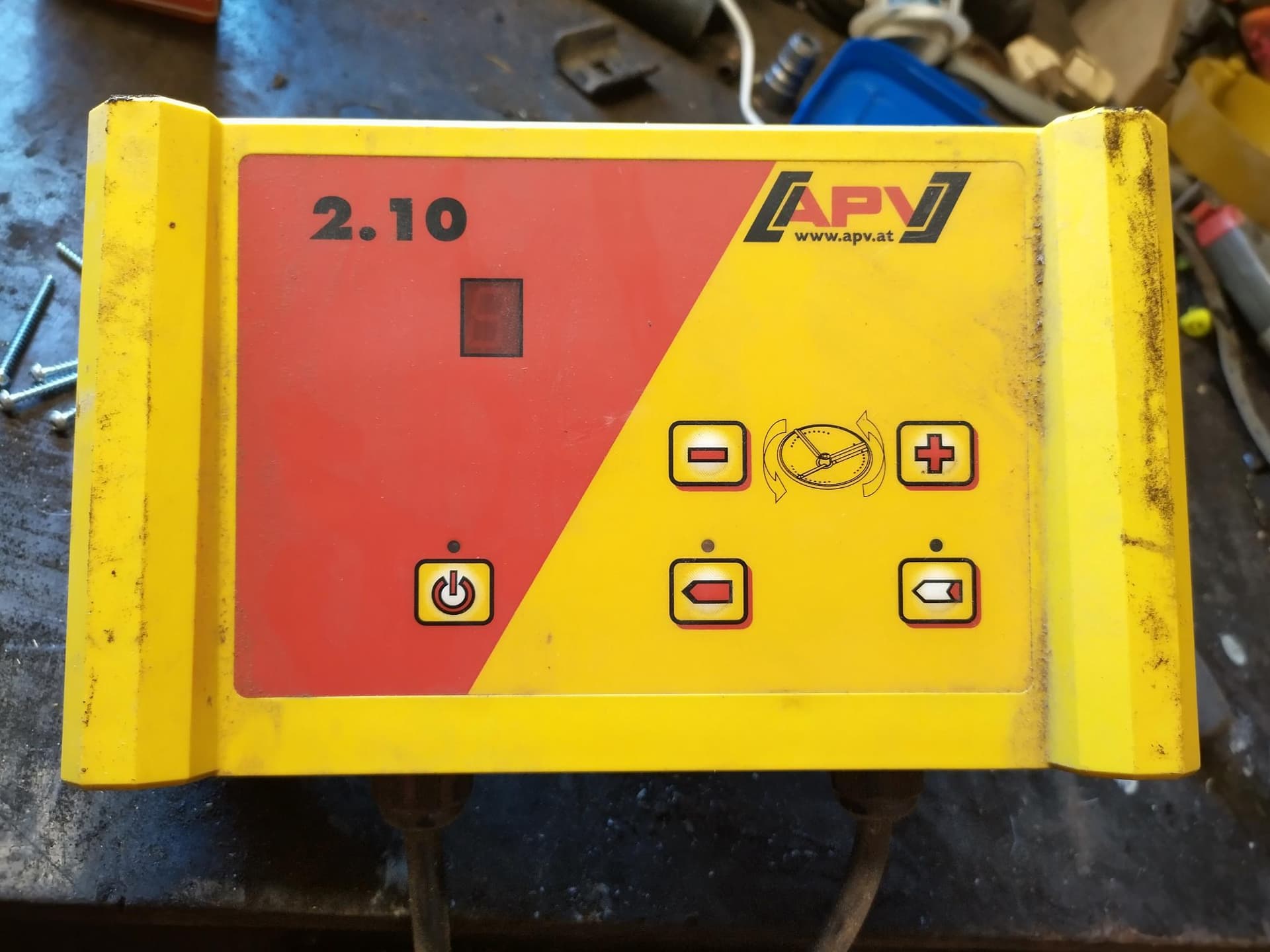
I plan to use the section control board from autosteer.cc to open/close the seed shaft on my APV seeder.
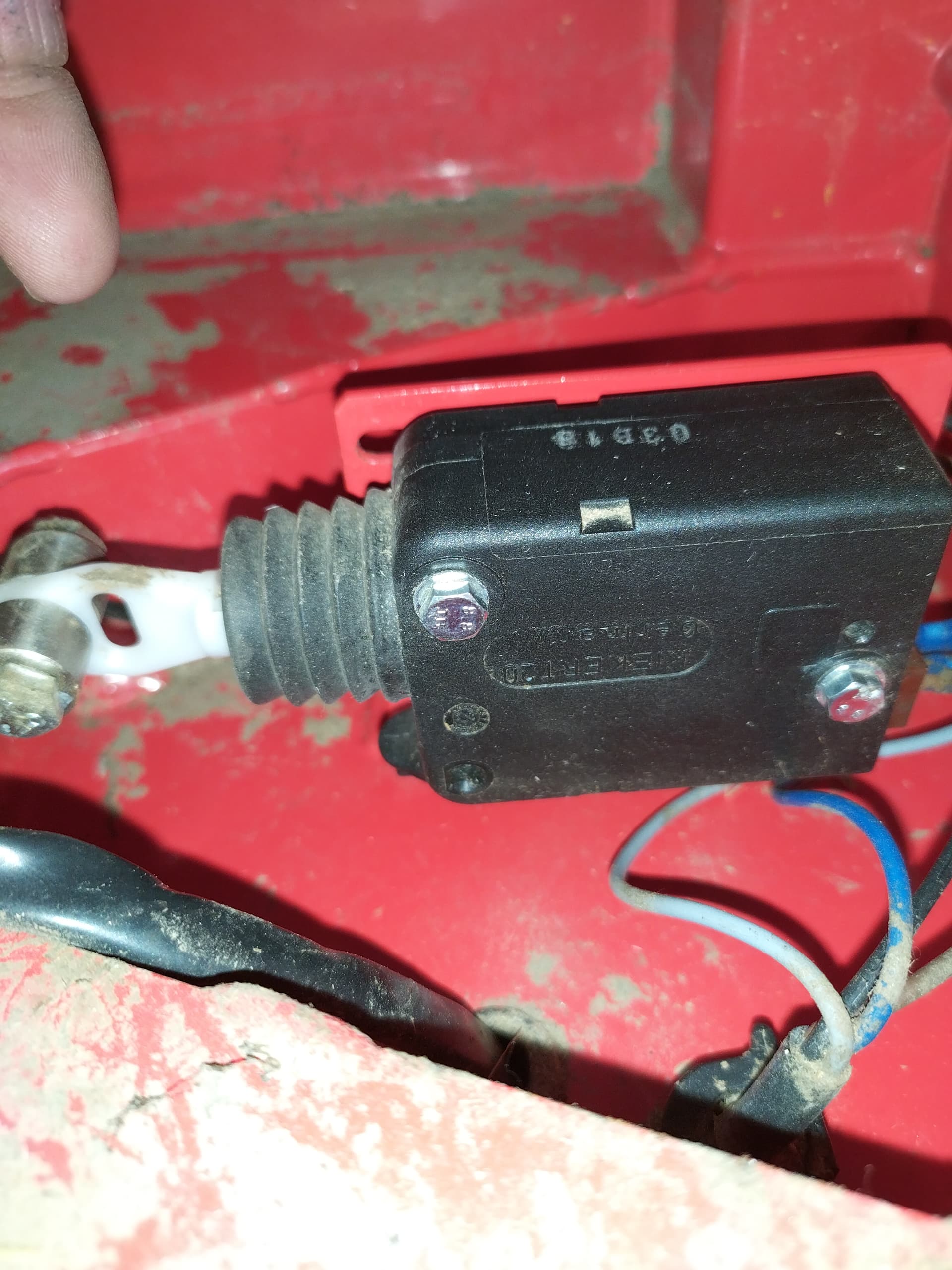
There’s 2 cables from the control box to the actuator on the seeder.
The open button sends 12v +/- and the close button sends -/+
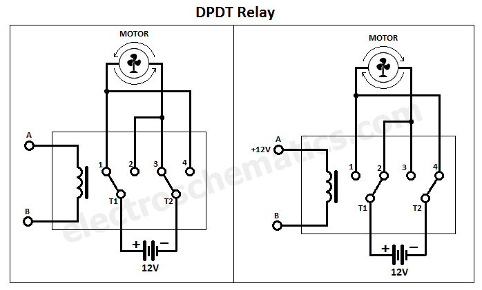
I’m not to familiar with this, but I know I have to use a DPDT realy for this to work.
How do I wire this, and still beeing able to use the controlbox?
Would any 12vDPDT realy work?
That’s one option, the motor will always turn in one direction until you activate the relay to reverse it. If you want control to stop the motor you have to add another relay for that.
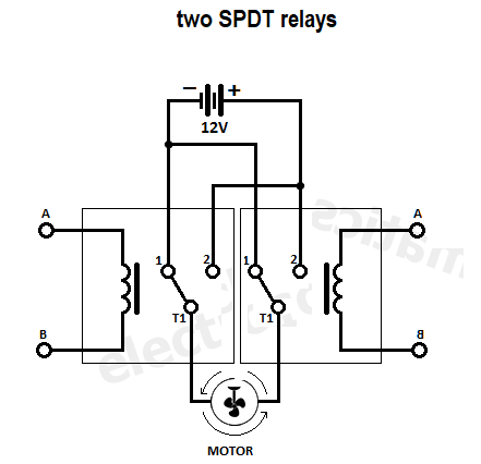
If you’re using two relays anyways, you can do it differently with two SPDT. When both relays are off or both are on, the motor doesn’t turn. You use one relay at a time for each direction.
1 Like
Thanks
Just for the record, I’m not trying to activate a motor. Its a solenoid. But it should be the same.
The solenoid stays in it’s position when power is cut. Given a +/- or -/+ it changes position.
If I understand correct, I can have either one DPDT or two identical SPDT to fix this.
I don’t have my autosteer kit at hand yet, but there are 8 relays on the section control board. Are they STDT relays?
If so, it seems to me another SPDT would be the best case???

Is it a motorized ball valve that is used to control flow rate or an on/off solenoid valve?
1 Like
on/of solenoid.
No liquid…
If it’s polarity switch, I think you are controling a motor to open close a gate valve (very similar to the flow valve as m_elias was describing).
Your schematic will work.
You will need a switch or relay to choose if you want to work with AOG (and send +12v 0V via the AOG relays) or with the original buttons (Auto/manual button). Maybe create a small extension cable with your modifications, easy to remove in case of problem.
1 Like
OK. Thanks.
I’ll get a few relays and see if I can create some smoke… 
I have the same controller for an APV machine.
Please post your solution 
1 Like
To limit the risk of smoke, you can put your full schematic here, we can have a look
1 Like
Just a thought:
Is it possible to hack some code so one can open with section relay 1 and close with section relay 2?
Just wire up the relays so both of them gets activated at the same time.
In case 1 is slower than the other you’ll just have -/- or +/+
lets say you have 2 relays:
NO / COM / NC
this by default give us -/+
if I switch relay 1 it becomes +/+
If I switch relay 2 bot not 1 it becomes -/-
If I switch both then it becomes +/-
in reality where SPDT relay boards has 3 connectors next to each other this looks like this:
- / out1 / - / - / out2 / +
And the trigger pin: trigger both with the same signal.
hope it helps
1 Like
I’m a total noob on this but I’m getting there…
Do you mean using one relay on the section board, and then buy one SPDT extra or using 2 relays on the section board?
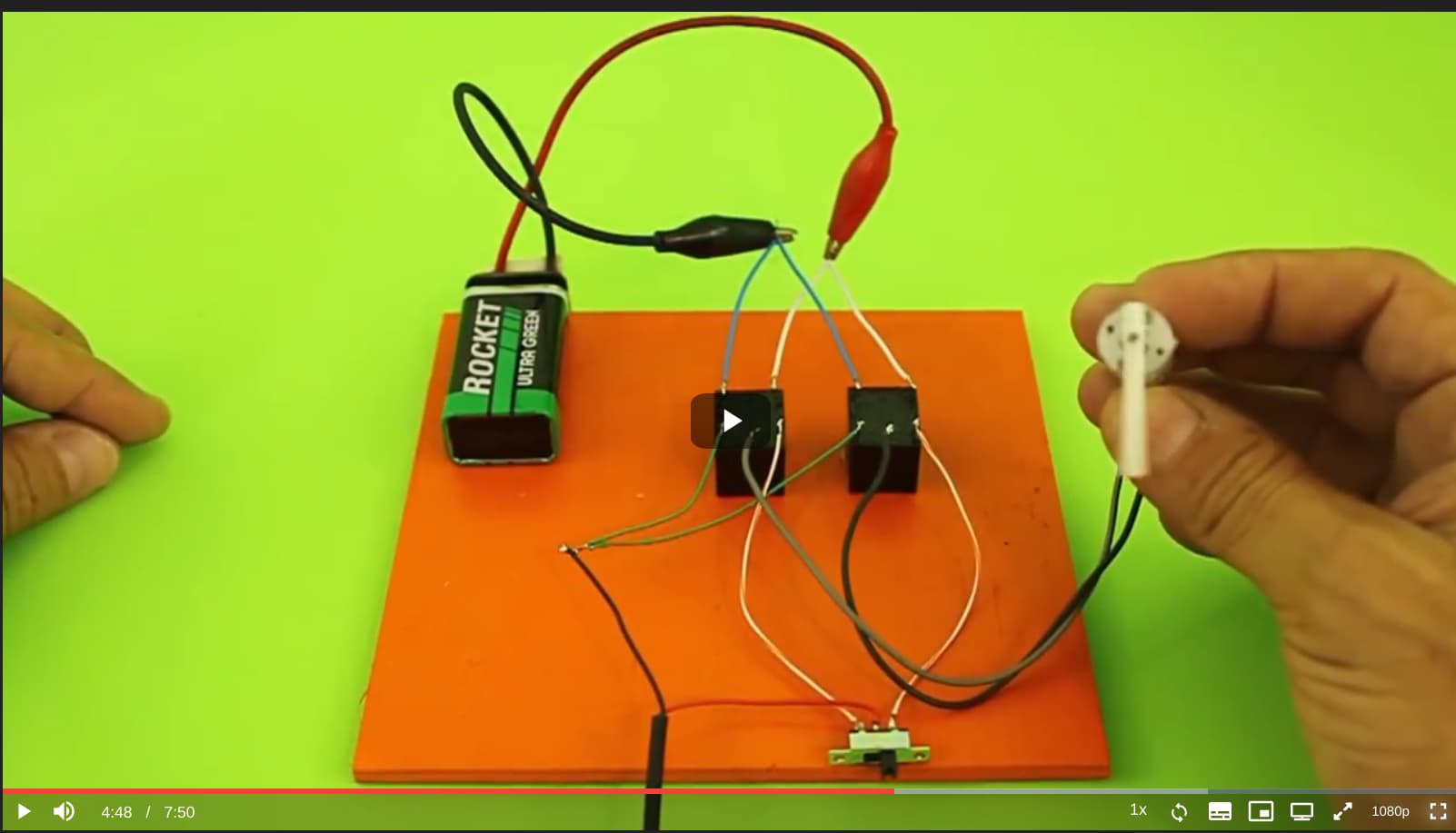
Trying to wire this up in TinkerCad to simulate it on a motor.
I found this example.
I understand this example, but how do this work with the section board?
The switch will not be there.
That switch is the main power switch.
You just need to trigger 2 relay at the same time.
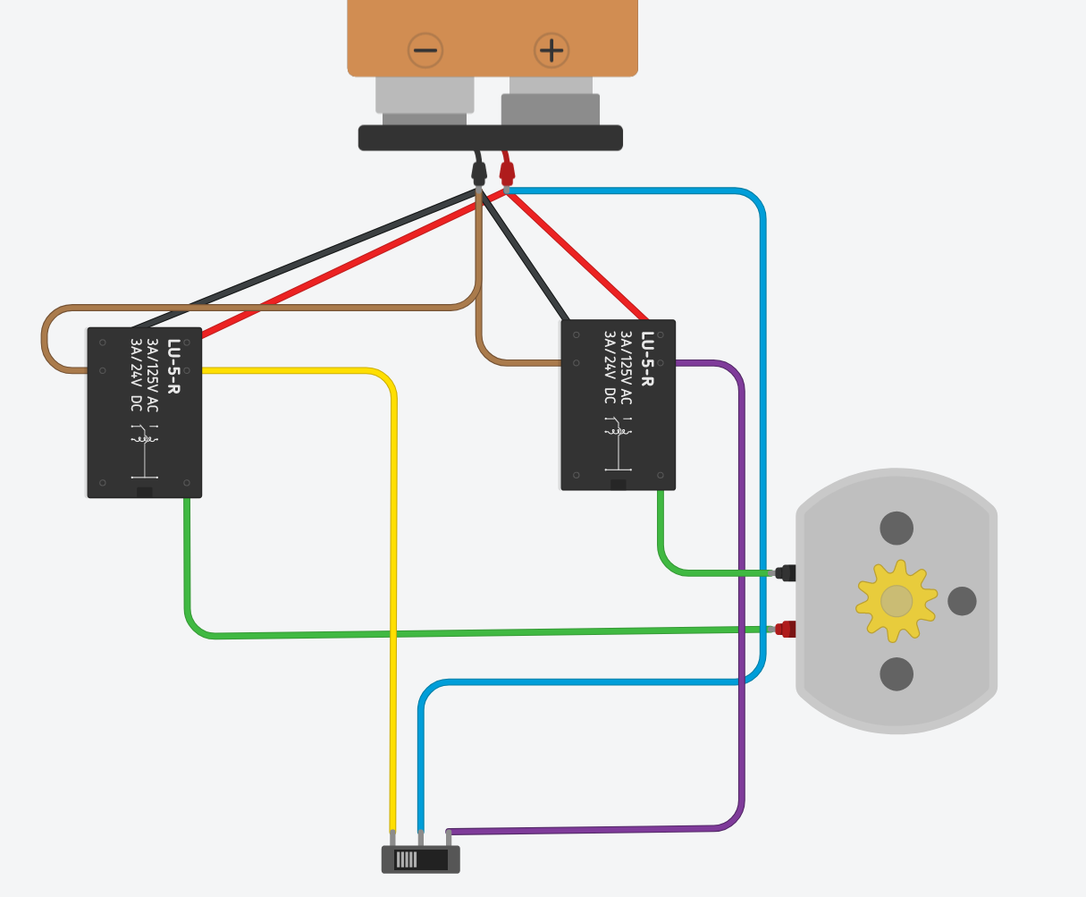
OK. So this works, spinning the motor both ways by operating the switch:
The relays are operating at the same time, but to different side.
The one below also works. Here I thinking that the lower relay is the on on the section control board.
This powers the motor all time, and change direction when I activate the relay
It will provide my actuator with power all the time, but I think the actuator can manage that.
I’m confused by the number of relays. Is this possible with just 2 relays?