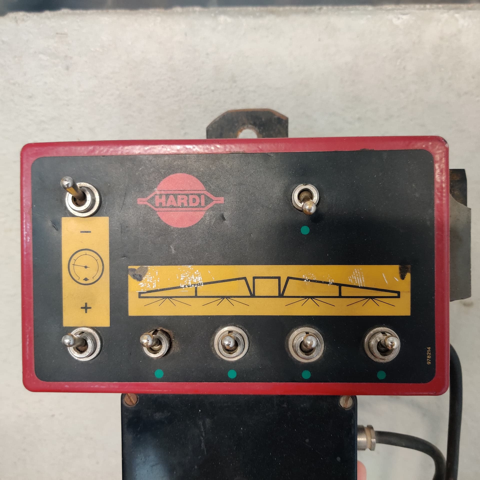
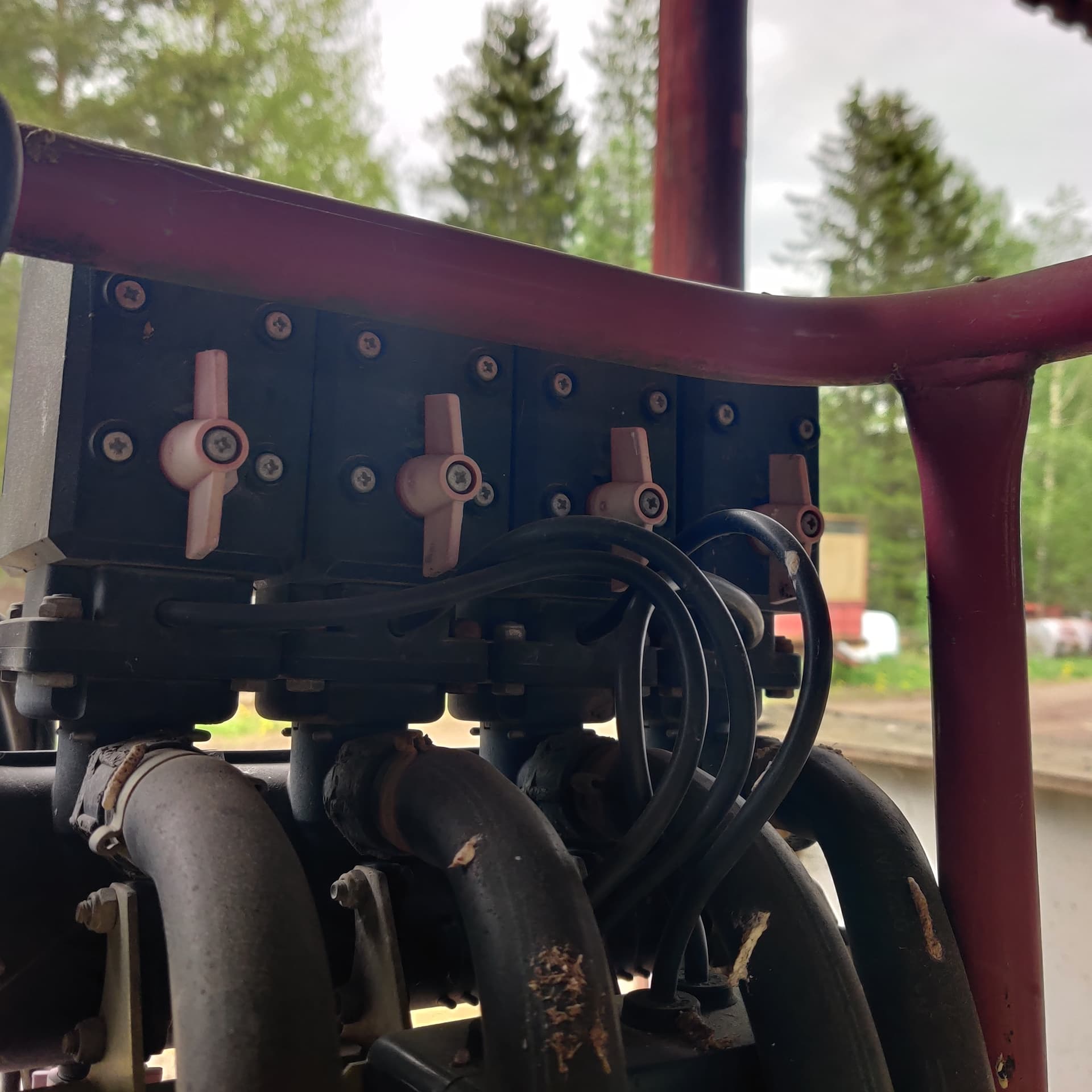
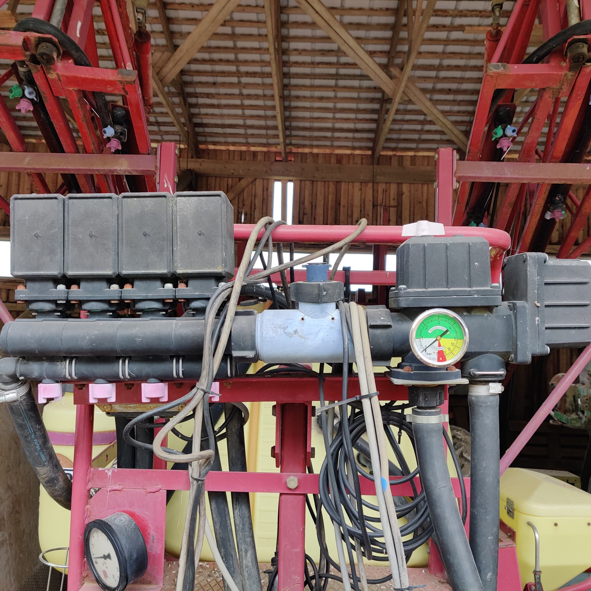
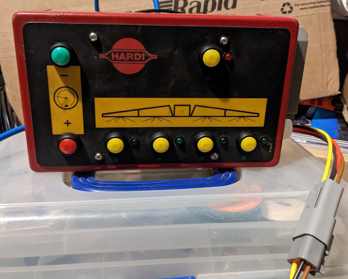
I would like to build section control to my Hardi sprayer. There is quite limited info on building one so what would I need to do that? I have autosteer with Kaupoimod 4.1, can I use arduino from that or does section control need separate one? Then I would need relay board, are these possible to buy complete or do I need to assemble one myself? Is there any wiring diagrams for section control? I’ll attach some pictures on my controller below.
1 Like

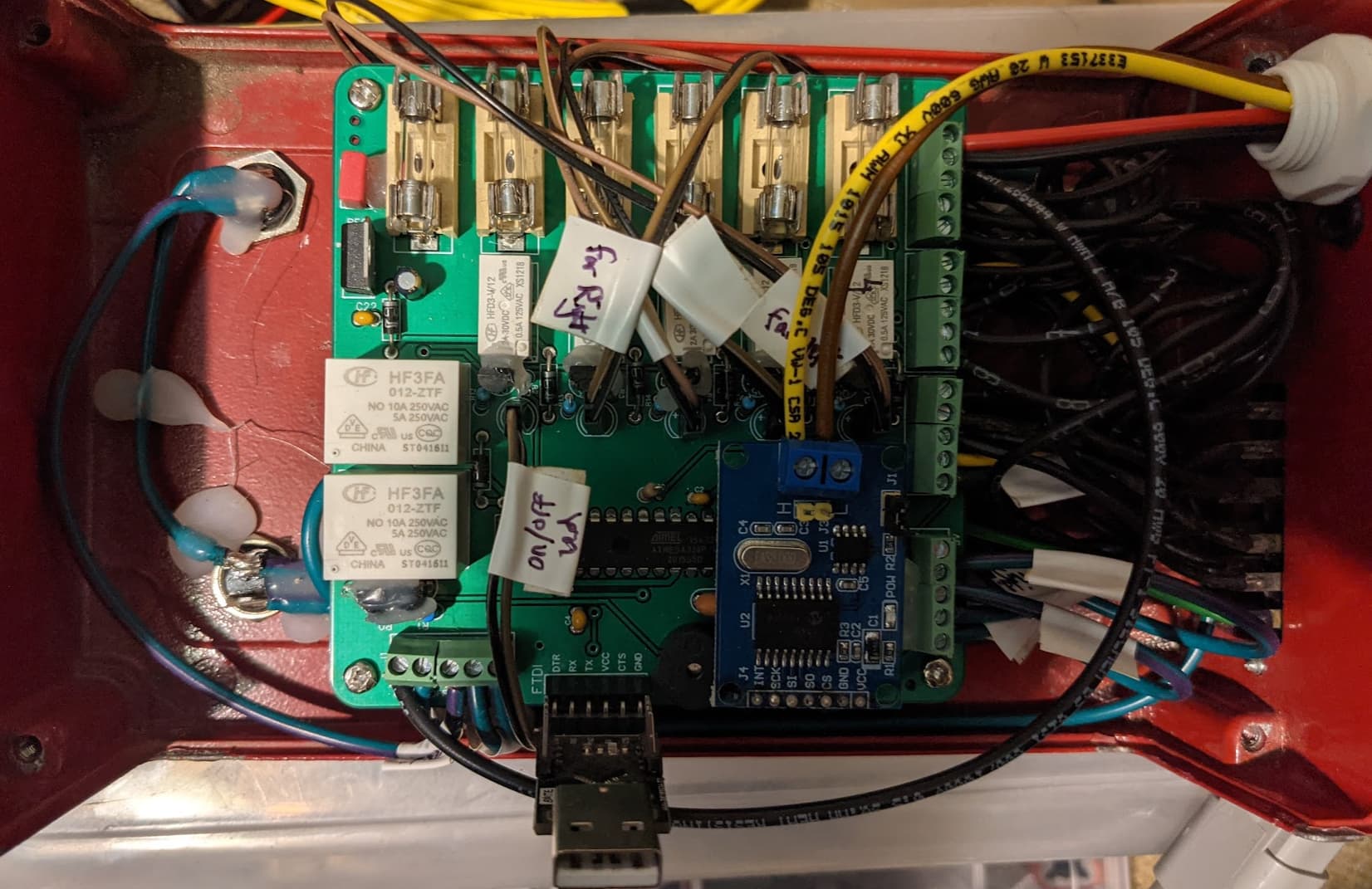
I converted my Hardi sprayer box to take section control from AgOpenGPS (replaced the internal PCB).
I dont know if it is the same with other sprayers, but the Hardi valve bodies work using a small motor with limit switches open/close the valves, so you need to use changeover relays rather than just on/off ones so you reverse the polarity for close vs open and vice versa.
/Edit: The pressure increase/decrease signals are slightly different in that they operate a single motor, with a NC signal to ground on the high side and the lowside. You then switch one side to 12 V to increase and the opposite side to 12 V to decrease pressure -see schematic in reply #20.
/
If I was going to do it again, I would just cut the sprayer cable and insert a 12 way deutsch plug between the manual switch box connector and the sprayer, and then create a seperate Section Control box that also used a 12 way deutsch connector. That way you always have the original control box as a backup.

Interesting. Where did you get your PCB layout?
I am working on a douve sprayer. Complete rebuild for all controlls.
Same there every section has a cable with 3 wires.
1 for gnd
and 2 for the motor that need to be switched around to open and close.
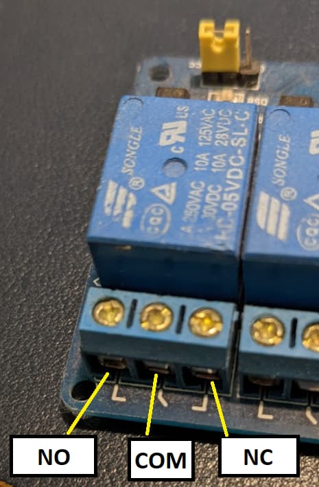
My advice would be to see if you can put relays in paralel with the switches and hook up an arduino to a relay board. like thise one.
Its the least destructive method. if it doesn’t work correctly you didn’t modify your actual sprayercontrols
So this wiring schematic doesn’t work for this polar switch? Or is the only difference the relay board type?
If you attach it to the valve directly this will indeed not work.
Then you need to create a H-bridge with relays.
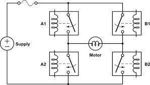
This can be done with 2 relays with both a normal open and normal closed pin.
If I am correct you can do it with this shematic by putting another relay board in parallel with the ones in the drawing you gave.
Then on relay board A you put
- positive to NO
- negative to NC
- 1 of the motor wires to the middle contact
and on relay module B you put - positive to NC
- negative to NO
- the other motor wire to the middle contact.
The valves will have a third wire that needs to go to ground (first find wich wire is wich)
Then if you power relay 1 on both relay boards section will open. And if you unpower that relay it will close.
Be very carefull of shorting ![]()
I also don’t think this is the adviced way of doing it if you don’t know exactly how the controls of the sprayer work. because I am not sure how this would react to the sprayer controls.
For me it seems easier to use the sprayer controls by puting the circuit you mention above and then putting the relays in paralel with those switches. This will make things less complex.
With motor type valve power should be cut off when you open section if power is applied continuously from relay motor is in stall all the time or there is limit switch? For just on off control its faster to just replace motor valves or add solenoid valves and use that schematic from section control AOG. (with pressure regulated boom)
If you add valves after original you have both systems operacional you would need to power solenoids all the time to use original but this way no modifaction to original control is made.
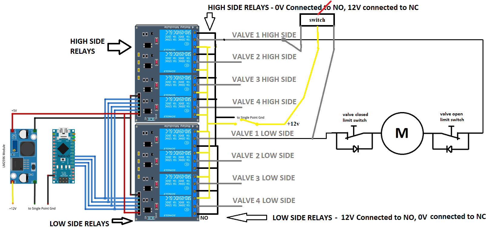
Not as shown in the AOG section control schematic, but you could build the circuit using those common relay boards (or 1x 8 relay board) as shown below (please excuse the MS Paint edit!):
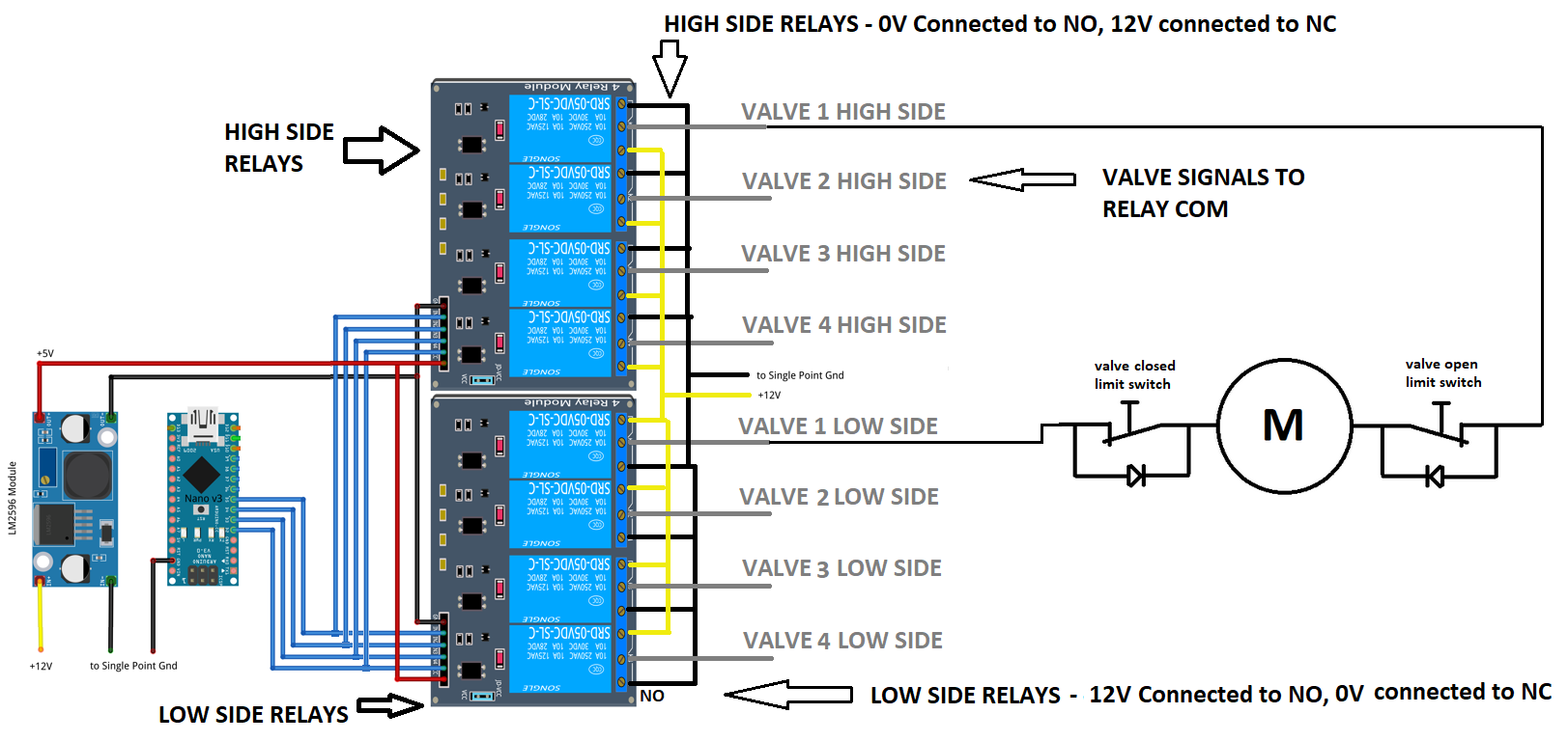
I have included the internal wiring of one of the valves on the right so you can see how the limit switches work. I suggest opening the back of your switch box and familiarising yourself with how it works using a multimeter in continuity and checking the switch contacts. If it is the same as mine, then the suggestions of wiring in parallel that have been made elsewhere in this thread will just result in shorting 12V to ground as soon as the relay and the manual switch are in opposite states.
The PCB design in my earlier post is my own, it has some oddities to it (e.g. canbus), but I am happy to share the EasyEDA files with you if you want to use it as a starting point (but the hard wired approach above would work fine).
2 Likes
Thank you for the schematic, it really clears things up!
Does this work with normal machine code or does it require modifications since every valve needs two relays?
As shown above should just work with the standard machine code from the support folder. You may need to switch which way the realys work depending on how the wiring up goes, but you could just switch 12v and 0v going into the relays to sort this. You might be able to reverse the relay logic from within AOG too?
Oh I just though of another thing. It is a good idea to add an inline fuse between the relays and one side of each valve (high side or low side - it doesn’t matter. I.e. one fuse per section). I used glass tube fuses so I could use the same ones as the standard Hardi switch box.
Otherwise if the limit switches fail the motor can damage it’s coupling with the valve
Would it also be possible to fit physical switches to this setup? So it would be a backup.
Physical switches are great backup for ali dirt cheap relay boards, its no fun returning from field with full sprayer because of failed relay. This way nano and relay boards are circumvented.
I made physical switches like this to directly drive solenoids after relay board should work for your motor type like this:
When you switch to manual mode turn off power to relays by switch and use manual switches direct, when in auto connect 12v to relays, and leave manual switches in middle position.
Ground not in relay but to single point away.
Thank you all for the answers.
@woody_matt you mentioned making separate cable for original box with 12 pole connector. Is there really only 12 connections? Because what I can make of this I get 8 connectors for sections, then 2 for main valve (or is this normal on off with 1 cable?), 2 for pressure control and then ground? If main valve is with normal on off instead of switching polarity and ground is coming from single connector then I can get 12 connections like you said.
Are the limit switches in the machine so I don’t have to do anything with them, just maybe add fuses to protect valves?
So I have these 4 sections. So I should add one simple on off switch that can cut power of from relays? Then add one 3 pole switch for every section wired like in your picture so 12V to one pole and then other 2 poles wired to valves?
Then it would be possible to just cut power off from relays and use switches to drive manually and just leave switches on central position when using automatic section control?
I’m not sure if I fully understand this, so correct me if I am wrong.
Actually you can’t just cut power to relays because you will use both NO and NC so on one side there will be backfeed and will result in turning off all of sections from one.
You need to isolate relay 12v+ separately to not have backfeed you can use 4PST switch for that.
You dont have to use 2 relay boards you can do this:
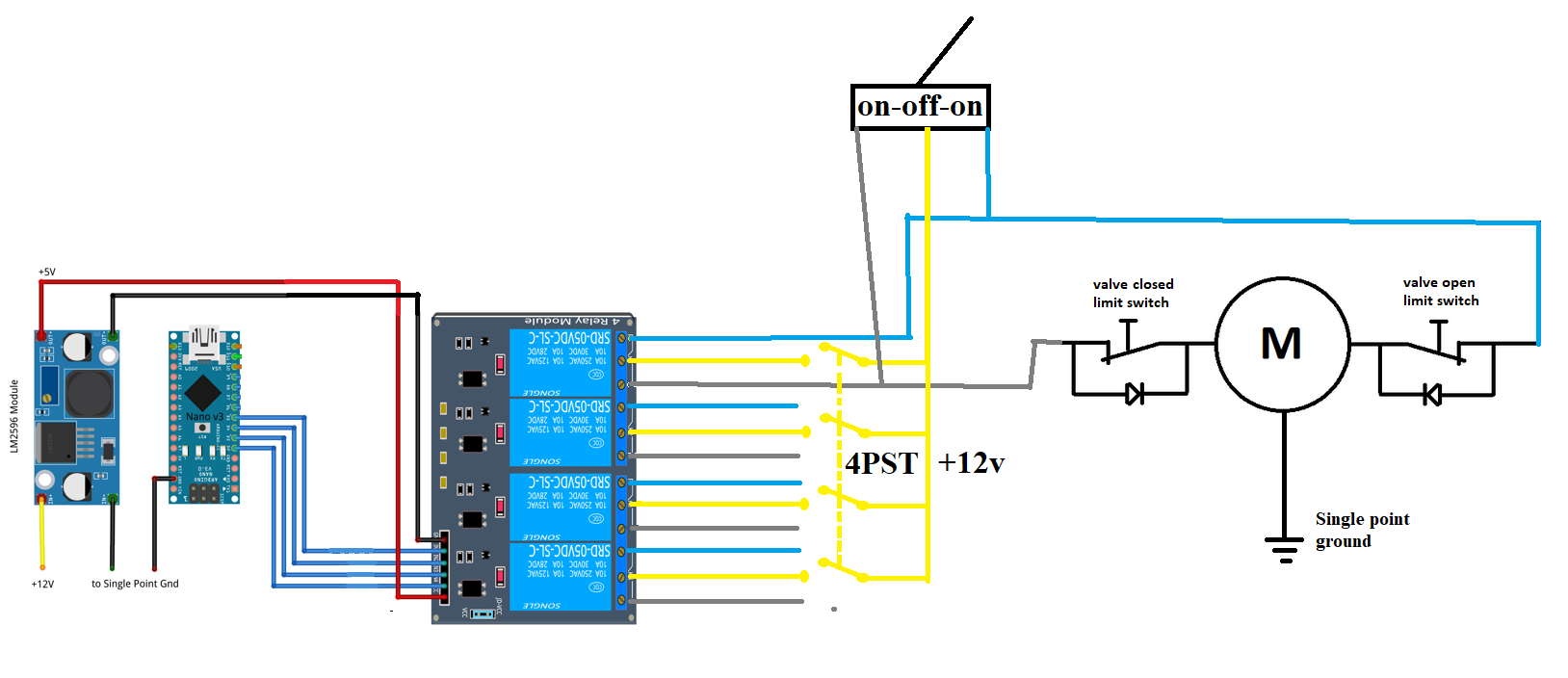
Switch blue and grey wires (NO/NC) to fit your needs.
Wouldn’t the 4 pst switch make it possible to accidentally have power on both motor directions at same time?
(If you forget setting manual switch in off before switching to relays with 4pst)
I would suggest 4pdt like this.
1 Like
Yes it is 12 signals, sorry I misread my schematic when I previously said that pressure increase and decrease were on off signals. These are still highside/lowside affairs the same as the sections, but both high side and low side default to ground, and then you increase or decrease by changing one side of the valve to 12 V. On my board it is wired like this:

with 9 and 10 being the highside and lowside feed to the pressure adjust motor (for me it was core 9 and 10 in the cable).
The main on off valve is wired the same as the individual sections.
Yes, the limit switches are integral inside the valve actuator housing, you just need the fuses to protect the motors using too much torque and damaging the valve.