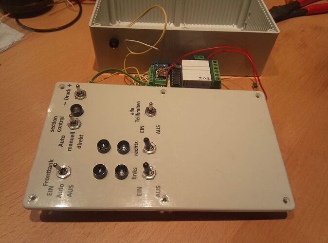
Hi,
I have modified the code for AgOpenGPS 4.2.0.x
is also for ESP32 DevKit to connect the sections relays over bluetooth.
   /*
    * This program only turns the relays for section control
    * On and Off. Connect to the Relay Port in AgOpenGPS
    */

  //loop time variables in microseconds
  #include "BluetoothSerial.h"
  #include <EEPROM.h>
  #define EEP_Ident 0x4201
  BluetoothSerial ESP_BT;

    //Program counter reset
    void(* resetFunc) (void) = 0;


//pins on ESP32 devKit
  const int seccio1 = 27;
  const int seccio2 = 26;
  const int seccio3 = 25;
  const int seccio4 = 33;
  const int seccio5 = 32;

  //this is  a relay to enable a valve to despresurize all the sections, is enabled when all sections are off
  const int general = 21;


  //Variables for config - 0 is false
  struct Config {
  byte raiseTime = 2;
  byte lowerTime = 4;
  byte enableToolLift = 0;
  byte isRelayActiveHigh = 0; //if zero, active low (default)

  };  Config aogConfig;   //4 bytes

  const byte LOOP_TIME = 200; //5hz
  unsigned long lastTime = LOOP_TIME;
  unsigned long currentTime = LOOP_TIME;
  unsigned long fifthTime = 0;
  unsigned int count = 0;

  //Comm checks
  byte watchdogTimer = 0; //make sure we are talking to AOG
  byte serialResetTimer = 0; //if serial buffer is getting full, empty it

   //Communication with AgOpenGPS
  bool isDataFound = false, isSettingFound = false, isAogConfigFound = false, isRelayActiveHigh = true;
  int header = 0, tempHeader = 0, temp, EEread = 0;

  //The variables used for storage
  byte relayHi=0, relayLo = 0, gpsSpeed = 0, tramline = 0, tree = 0, uTurn = 0, hydLift = 0;

  byte raiseTimer = 0, lowerTimer = 0, lastTrigger = 0;

  //Raise and lower as D4 and D3
  #define RAISE 4
  #define LOWER 3

void setup()
  {
      Serial.begin(38400);
      ESP_BT.begin("AGOpenGPS_reles"); //Name of your Bluetooth Signal
      Serial.println("Bluetooth Device is Ready to Pair");
    //set the baud rate
     //Serial.begin(38400);
     while (!ESP_BT.available()) { ; } // wait for serial port to connect. Needed for native USB

     EEPROM.get(0, EEread);              // read identifier

  if (EEread != EEP_Ident)   // check on first start and write EEPROM
  {
    EEPROM.put(0, EEP_Ident);
    EEPROM.put(6, aogConfig);
  }
  else
  {
    EEPROM.get(6, aogConfig);
  }

  //set the pins to be outputs (pin numbers)
  pinMode(LOWER, OUTPUT);
  pinMode(RAISE, OUTPUT);

  pinMode(seccio1, OUTPUT);
  pinMode(seccio2, OUTPUT);
  pinMode(seccio3, OUTPUT);
  pinMode(seccio4, OUTPUT);
  pinMode(seccio5, OUTPUT);
  pinMode(general, OUTPUT);

//set all relays sections to OFF exept despresurize valve
  digitalWrite(seccio1, LOW);
  digitalWrite(seccio2, LOW);
  digitalWrite(seccio3, LOW);
  digitalWrite(seccio4, LOW);
  digitalWrite(seccio5, LOW);
  digitalWrite(general, HIGH);
}

void loop()
{
  //Loop triggers every 200 msec and sends back gyro heading, and roll, steer angle etc

  currentTime = millis();
  unsigned int time = currentTime;

  if (currentTime - lastTime >= LOOP_TIME)
  {
    lastTime = currentTime;

    //If connection lost to AgOpenGPS, the watchdog will count up
    if (watchdogTimer++ > 250) watchdogTimer = 12;

    //clean out serial buffer to prevent buffer overflow
    if (serialResetTimer++ > 20)
    {
      while (ESP_BT.available() > 0) char t = ESP_BT.read();
      serialResetTimer = 0;
    }

    if (watchdogTimer > 10)
    {
      relayLo = 0;
      relayHi = 0;
    }

    //hydraulic lift

    if (hydLift != lastTrigger && (hydLift == 1 || hydLift == 2))
    {
      lastTrigger = hydLift;
      lowerTimer = 0;
      raiseTimer = 0;

      //200 msec per frame so 5 per second
      switch (hydLift)
      {
        //lower
        case 1:
          lowerTimer = aogConfig.lowerTime * 5;
        break;

        //raise
        case 2:
          raiseTimer = aogConfig.raiseTime * 5;
        break;
      }
    }

    //countdown if not zero, make sure up only
    if (raiseTimer)
    {
      raiseTimer--;
      lowerTimer = 0;
    }
    if (lowerTimer) lowerTimer--;

    //if anything wrong, shut off hydraulics, reset last
    if ((hydLift != 1 && hydLift != 2) || watchdogTimer > 10 ) //|| gpsSpeed < 2)
    {
      lowerTimer = 0;
      raiseTimer = 0;
      lastTrigger = 0;
    }

    //section relays
    SetRelays();

    //Send data back to agopenGPS
    ESP_BT.print(127); //steering switch status
    ESP_BT.print(",");
    ESP_BT.print(248); //steering switch status
    ESP_BT.print(",");
    ESP_BT.print(raiseTimer); //steering switch status
    ESP_BT.print(",");
    ESP_BT.print(lowerTimer); //steering switch status
    ESP_BT.print(",");
    ESP_BT.print(hydLift); //steering switch status
    ESP_BT.print(",");
    ESP_BT.print(aogConfig.isRelayActiveHigh); //steering switch status
    ESP_BT.print(",0,0,0,");
    ESP_BT.println(0);

   /*
    Serial.print(",");

   Serial.print(gpsSpeed); //steering switch status
    Serial.print(",");

   Serial.print(hydLift); //steering switch status
    Serial.print(",");

   Serial.print(lastTrigger); //steering switch status
    Serial.print(",");

   Serial.println(aogConfig.lowerTime); //steering switch status
   */

   ESP_BT.flush();   // flush out buffer

  } //end of timed loop

  //****************************************************************************************
  //This runs continuously, outside of the timed loop, keeps checking UART for new data
        // PGN - 32762 - 127.250 0x7FFA
        //public int mdHeaderHi, mdHeaderLo = 1, mdSectionControlByteHi = 2, mdSectionControlByteLo = 3,
        //mdSpeedXFour = 4, mdUTurn = 5, mdTree = 6, mdHydLift = 7, md8 = 8, md9 = 9;
  if (ESP_BT.available() > 0 && !isDataFound && !isAogConfigFound) //find the header, 127H + 254L = 32766
  {
    int temp = ESP_BT.read();
    header = tempHeader << 8 | temp;                //high,low bytes to make int
    tempHeader = temp;                              //save for next time
    if (header == 32762) isDataFound = true;        //Do we have a match?
    if (header == 32760) isAogConfigFound = true;     //Do we have a match?
  }

  //Data Header has been found, so the next 6 bytes are the data
  if (ESP_BT.available() > 7 && isDataFound)
  {
    isDataFound = false;
    relayHi = ESP_BT.read();
    relayLo = ESP_BT.read();          // read relay control from AgOpenGPS
    gpsSpeed = ESP_BT.read() >> 2;  //actual speed times 4, single byte
    uTurn = ESP_BT.read();
    tree = ESP_BT.read();
    hydLift = ESP_BT.read();

    //just get the rest of bytes
    ESP_BT.read();   //high,low bytes
    ESP_BT.read();

    //reset watchdog
    watchdogTimer = 0;

    //Reset serial Watchdog
    serialResetTimer = 0;
  }

   //Arduino Config Header has been found, so the next 8 bytes are the data
  if (ESP_BT.available() > 7 && isAogConfigFound)
  {
    isAogConfigFound = false;

    aogConfig.raiseTime = ESP_BT.read();
    aogConfig.lowerTime = ESP_BT.read();
    aogConfig.enableToolLift = ESP_BT.read();

    //set1
    byte sett = ESP_BT.read();  //setting0
    if (bitRead(sett,0)) aogConfig.isRelayActiveHigh = 1; else aogConfig.isRelayActiveHigh = 0;

    ESP_BT.read();
    ESP_BT.read();
    ESP_BT.read();
    ESP_BT.read();

    //save in EEPROM and restart
    EEPROM.put(6, aogConfig);
    resetFunc();
  }
}

  void SetRelays(void)

 {
    if (aogConfig.isRelayActiveHigh)
    {
      //active low
     /* if (lowerTimer) bitClear(PORTD, LOWER); //Digital Pin D3
      else bitSet(PORTD, LOWER);

      if (raiseTimer) bitClear(PORTD, RAISE); //Digital Pin D4
      else bitSet(PORTD, RAISE);
     */

      Serial.println(relayLo);

      if (bitRead(relayLo,0)) digitalWrite(seccio1, LOW); //Digital Pin 5
      else digitalWrite(seccio1, HIGH);
      if (bitRead(relayLo,1)) digitalWrite(seccio2, LOW); //Digital Pin 6
      else digitalWrite(seccio2, HIGH);
      if (bitRead(relayLo,2)) digitalWrite(seccio3, LOW); //Digital Pin 7
      else digitalWrite(seccio3, HIGH);
      if (bitRead(relayLo,3)) digitalWrite(seccio4, LOW); //Digital Pin 8
      else digitalWrite(seccio4, HIGH);
      if (bitRead(relayLo,4)) digitalWrite(seccio5, LOW); //Digital Pin 9
      else digitalWrite(seccio5, HIGH);

      /*if (bitRead(relayLo,6)) bitClear(PORTB, 3); //Digital Pin 11
      else bitSet(PORTB, 3);
      if (bitRead(relayLo,7)) bitClear(PORTB, 4); //Digital Pin 12
      else bitSet(PORTB, 4); */
      if (relayLo == 0) digitalWrite(general, LOW);
      else digitalWrite(general, HIGH);

    }
    else //active high
    {
    /*  if (lowerTimer) bitSet(PORTD, LOWER); //Digital Pin D3
      else bitClear(PORTD, LOWER);

      if (raiseTimer) bitSet(PORTD, RAISE); //Digital Pin D4
      else bitClear(PORTD, RAISE);
 */
      Serial.println(relayLo);

      if (bitRead(relayLo,0)) digitalWrite(seccio1, HIGH);  //Digital Pin 5
      else digitalWrite(seccio1, LOW);
      if (bitRead(relayLo,1)) digitalWrite(seccio2, HIGH); //Digital Pin 6
      else digitalWrite(seccio2, LOW);
      if (bitRead(relayLo,2)) digitalWrite(seccio3, HIGH); //Digital Pin 7
      else digitalWrite(seccio3, LOW);
      if (bitRead(relayLo,3)) digitalWrite(seccio4, HIGH); //Digital Pin 8
      else digitalWrite(seccio4, LOW);
      if (bitRead(relayLo,4)) digitalWrite(seccio5, HIGH); //Digital Pin 9
      else digitalWrite(seccio5, LOW);

      /*
      if (bitRead(relayLo,5)) bitSet(PORTB, 2); //Digital Pin 10
      else bitClear(PORTB, 2);
      if (bitRead(relayLo,6)) bitSet(PORTB, 3); //Digital Pin 11
      else bitClear(PORTB, 3);
      if (bitRead(relayLo,7)) bitSet(PORTB, 4); //Digital Pin 12
      else bitClear(PORTB, 4);  */
      if (relayLo == 0) digitalWrite(general, HIGH);
      else digitalWrite(general, LOW);
    }
  }

