yes first just with one.
Your wiring is also not working.
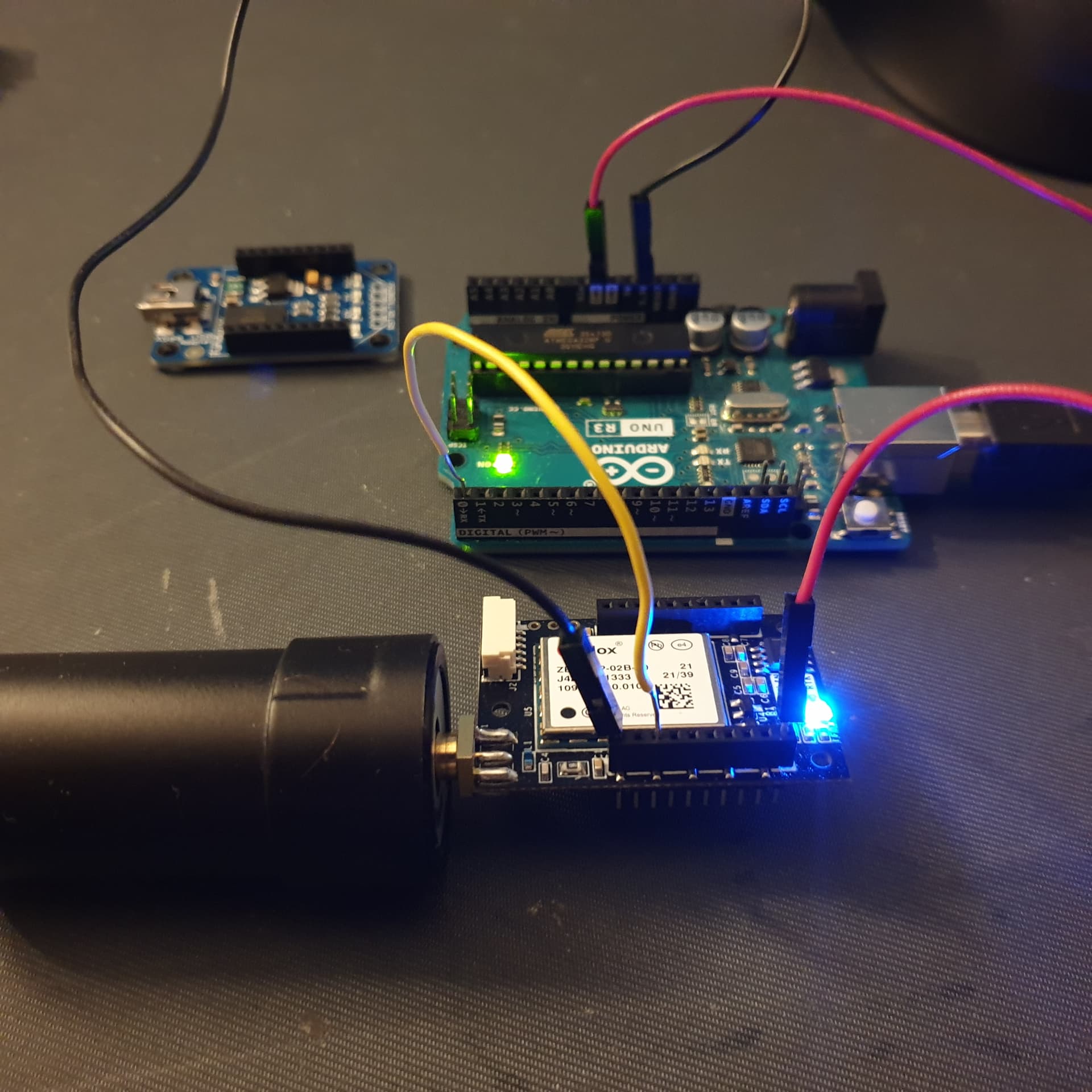
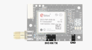
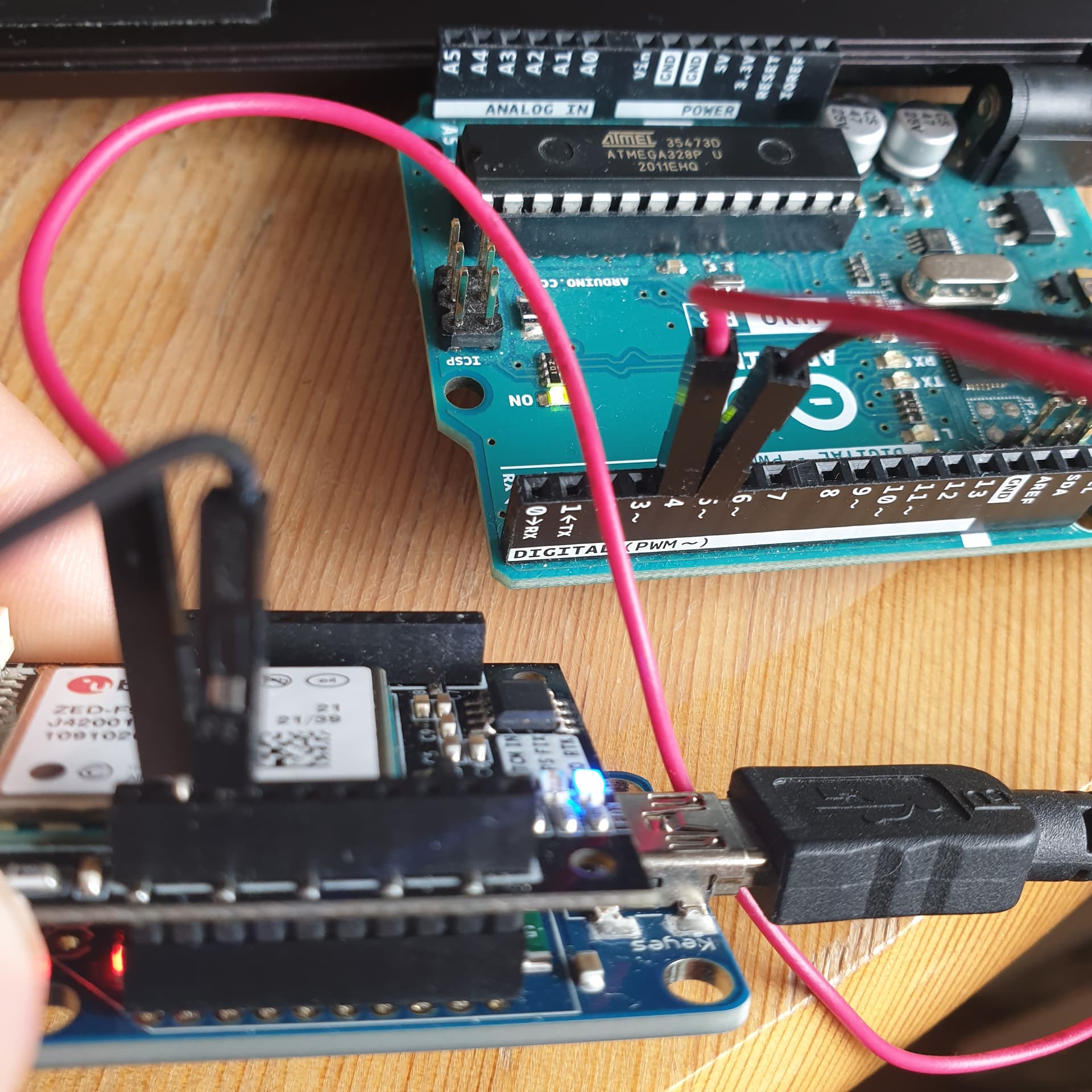
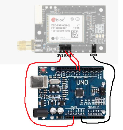
Now im trying it with power with the Xbee Adapter and wire it like in the picture.
i use the tinygpsplus Fullexampel code
#include <TinyGPS.h>
#include <SoftwareSerial.h>
#include <TinyGPS.h>
/* This sample code demonstrates the normal use of a TinyGPS object.
It requires the use of SoftwareSerial, and assumes that you have a
4800-baud serial GPS device hooked up on pins 4(rx) and 3(tx).
*/
TinyGPS gps;
SoftwareSerial ss(0, 1);
void setup()
{
Serial.begin(115200);
ss.begin(115200);
Serial.print("Simple TinyGPS library v. "); Serial.println(TinyGPS::library_version());
Serial.println(“by Mikal Hart”);
Serial.println();
}
void loop()
{
bool newData = false;
unsigned long chars;
unsigned short sentences, failed;
// For one second we parse GPS data and report some key values
for (unsigned long start = millis(); millis() - start < 1000;)
{
while (ss.available())
{
char c = ss.read();
// Serial.write(c); // uncomment this line if you want to see the GPS data flowing
if (gps.encode(c)) // Did a new valid sentence come in?
newData = true;
}
}
if (newData)
{
float flat, flon;
unsigned long age;
gps.f_get_position(&flat, &flon, &age);
Serial.print(“LAT=”);
Serial.print(flat == TinyGPS::GPS_INVALID_F_ANGLE ? 0.0 : flat, 6);
Serial.print(" LON=“);
Serial.print(flon == TinyGPS::GPS_INVALID_F_ANGLE ? 0.0 : flon, 6);
Serial.print(” SAT=“);
Serial.print(gps.satellites() == TinyGPS::GPS_INVALID_SATELLITES ? 0 : gps.satellites());
Serial.print(” PREC=");
Serial.print(gps.hdop() == TinyGPS::GPS_INVALID_HDOP ? 0 : gps.hdop());
}
gps.stats(&chars, &sentences, &failed);
Serial.print(" CHARS=“);
Serial.print(chars);
Serial.print(” SENTENCES=“);
Serial.print(sentences);
Serial.print(” CSUM ERR=“);
Serial.println(failed);
if (chars == 0)
Serial.println(”** No characters received from GPS: check wiring **");
}
i changed the baud to 115200 because the f9f use it.
but in the serial monitor is only:
14:46:56.210 → **** ***** ********** *********** **** ********** ******** **** ****** ****** ***** *** ******** ****** *** 0 0 0
14:46:57.201 → No GPS data received: check wiring
14:46:57.201 → **** ***** ********** *********** **** ********** ******** **** ****** ****** ***** *** ******** ****** *** 0 0 0
14:46:58.252 → No GPS data received: check wiring
14:46:58.252 → **** ***** ********** *********** **** ********** ******** **** ****** ****** ***** *** ******** ****** *** 0 0 0
14:46:59.255 → No GPS data received: check wiring