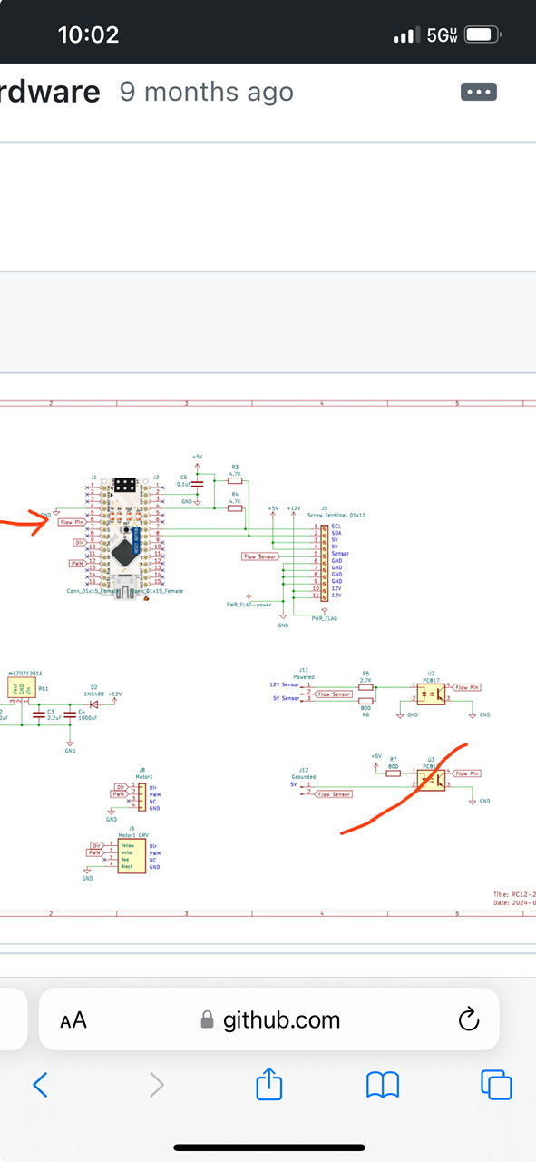
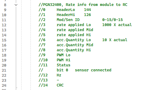
I have built an RC12 and an RC12-2 board and used them with the rate control app by SK21. Both have worked well. If you just want the rate calculated, both of those board use an arduino nano plugged into a enc28j60 Ethernet shield. One easy option would be to get a nano, load the program SK21 wrote on it for the RC12-2 board. Plug the nano into the Ethernet shield so it can connect to the rate control app. At that point you would just need to provide 5v to the VIN pin on the nano and a ground. Pin D3 is the flow pin. It needs to be grounded every time the flow meter pulses. You may need to use an opticoupler to invert the signal if your flow meter pluses a positive voltage output. That would be a half way easy solution. I do have a spare RC-12 board on hand if you want it to make mounting easier you can have it for the price of postage.
(The red slash through the opricoupler in the Lower right hand corner was a mistake. I was just trying to make a mark by the flow pin by the nano on the schematic)
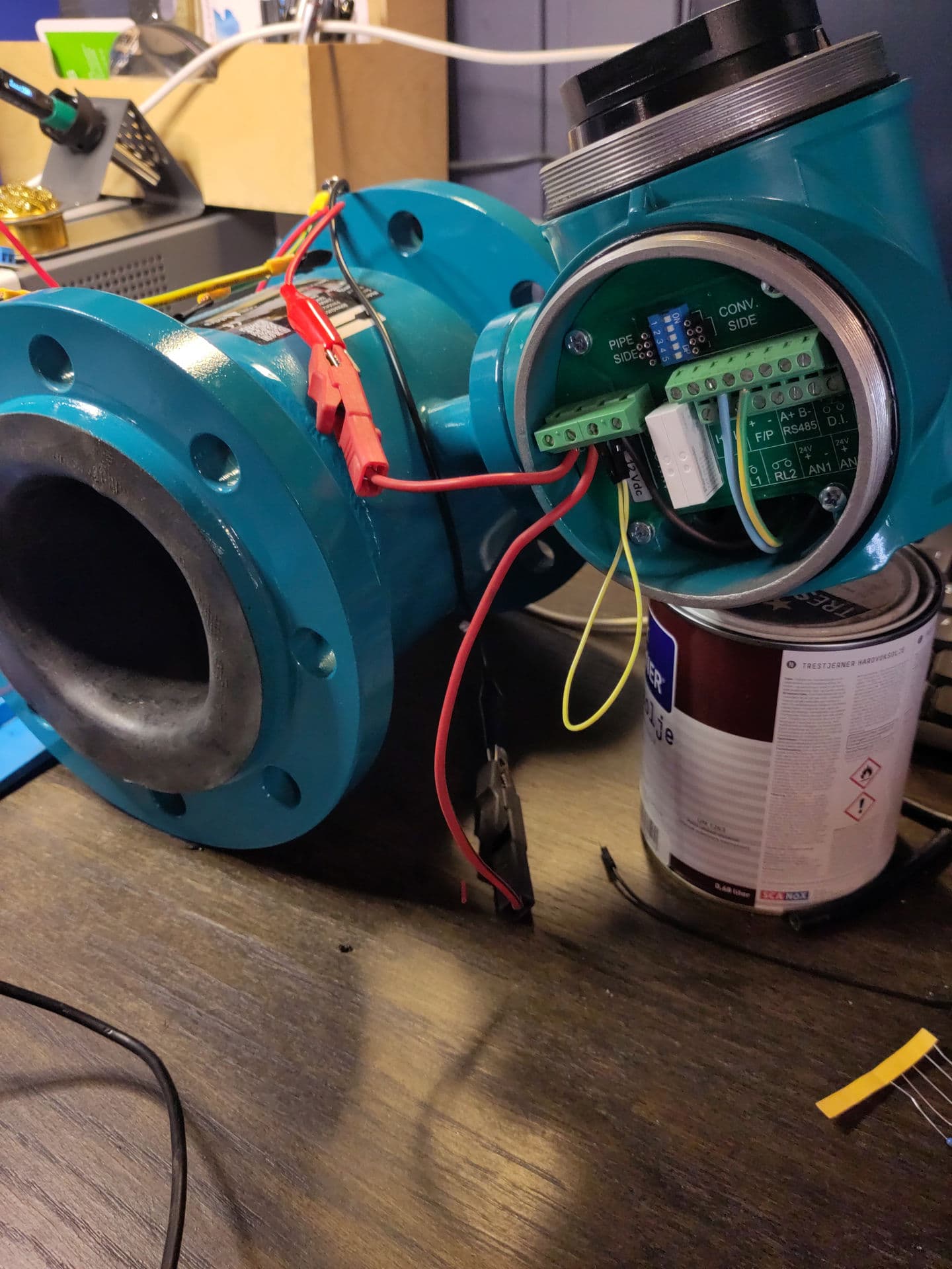
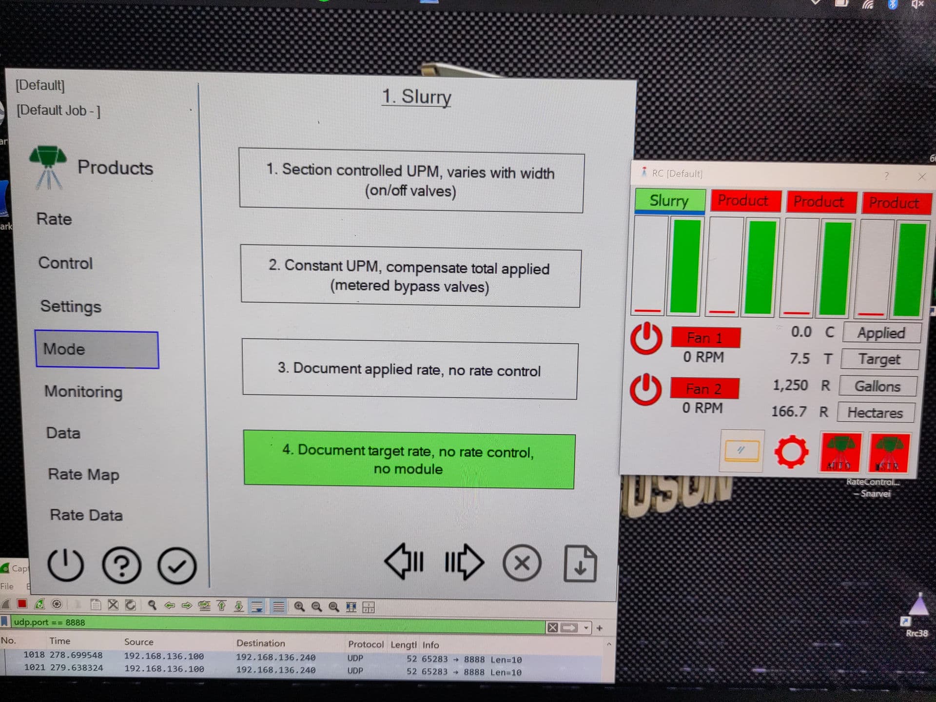
Finally made some progress on this.
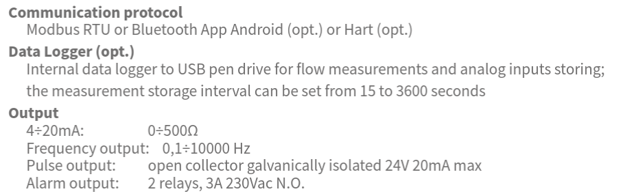
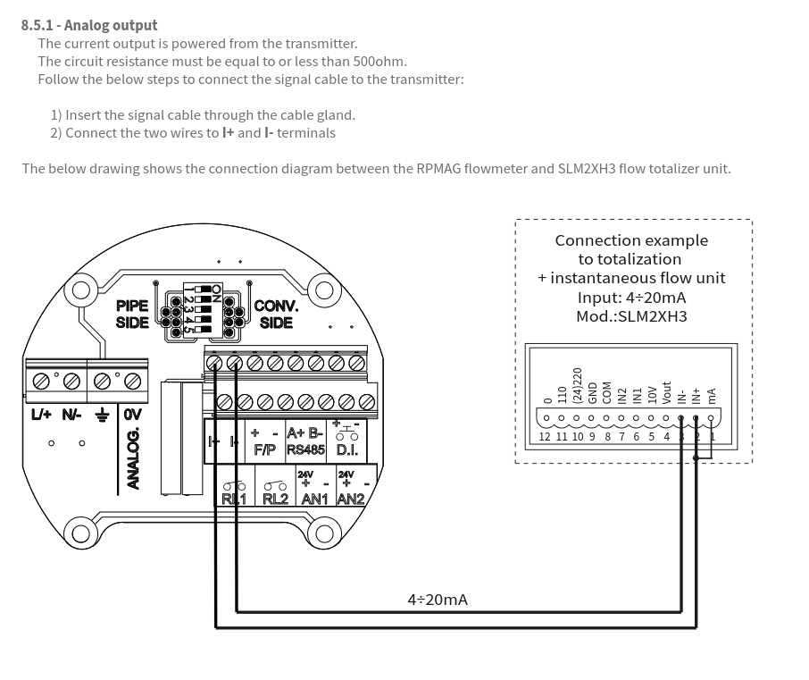
The flowmeter has several methods to read flow. I ended up with frequence/pulse readings.
Steep learning curve for me. Meter is supplied with 12v and outputs 24v.
First I tried to read the flow when the meter was in frequency test mode, but I had no luck with that. Maybe the NodeMCU 8266 is to slow. Flowrates was far out. Max and min flow was ok, but in between was way above max.
Took down the voltage to around 3v with a variable resistor, and then I could read pulses on my NodeMcu 8266.
Can’t find default values for liter per pulse, so I’ll have to compare with the flowmeters display, and adjust.
It’s a start. Planning to read the flow in a webapp on my mobile for this season.