Some guidance in my pcb build

Building a board here and I’m not 100% sure I know what I’m doing. All I’m going for is just basic autosteer, no section control

Start off questions are

  1. Can I run one antenna on this board or does it have to be dual
  2. Other then the f9p boards, do I have everything I need to get started or is there a board missing bellow the cytron board?
  3. How/where do I wire in my wheel angle sensor? Do I do that through the ampseal plug.

Thanks in advance for your help

  1. Depends on the firmware you flash. Yes it can do single and dual antenna.
  2. From the picture you are only missing F9P board and most important 2 voltage regulators, the board wont power on.
  3. Yes WAS goes on ampseal connector, pin 1 (+5v), 2 (signal) and 4 (gnd)
2 Likes

You also have the 6 ethernet pins missing from the teensy, with some luck the female socket underneath it will be fitted already

3 Likes

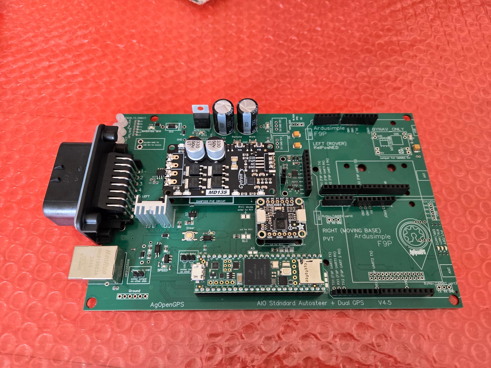
Also the header pins for the f9p have been soldierd in with 2 joins which will make trying to get the f9p pins lined up a bit tricky so take you time and ensure they mate up correctly

Thanks… missed that step. Yes the female socket is fitted already.

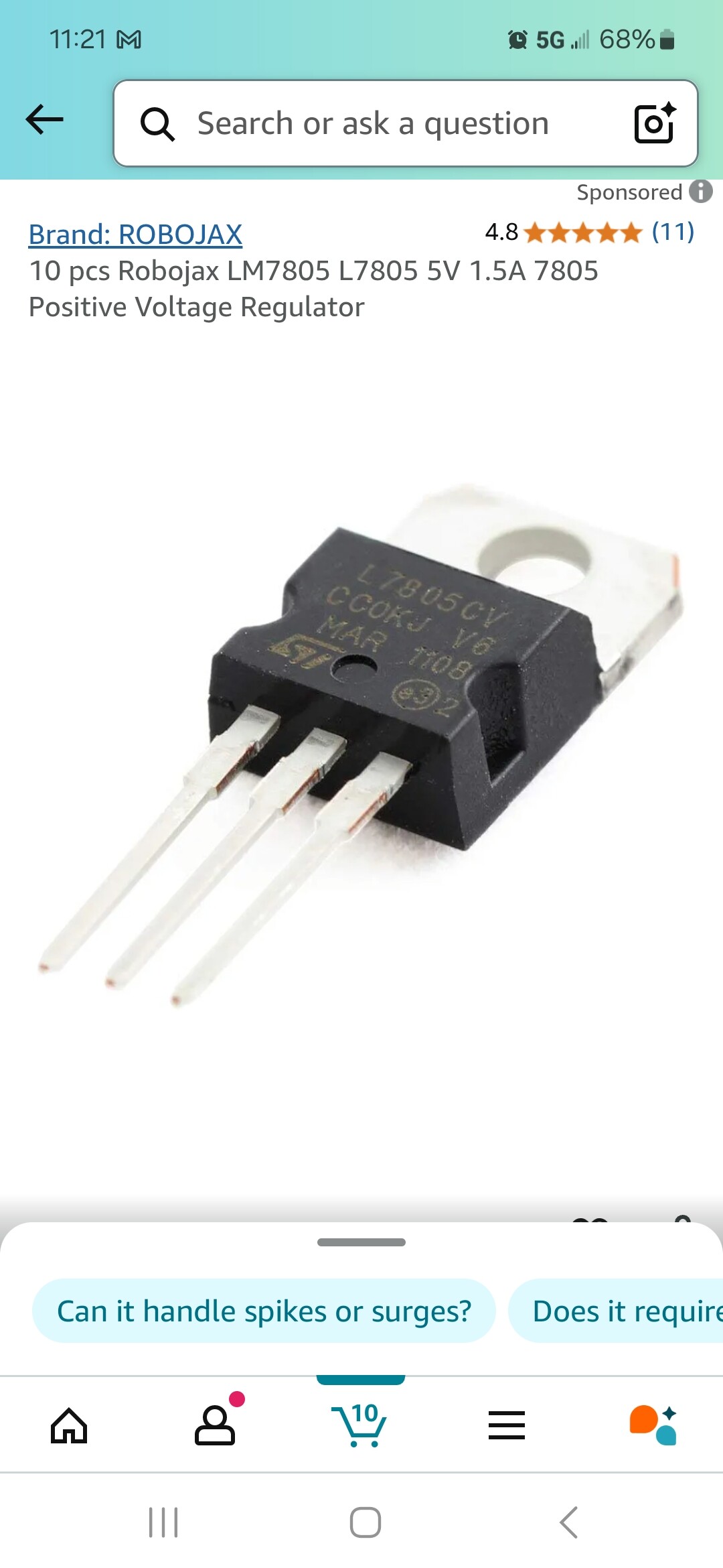
Yeah I’ve got the f9p boards already… just don’t have the headers soldered yet. I can’t seem to find any information regarding the voltage regulators on the AgOpenGPS Documentation page, but I see where they go on the board. Would these work, or do you have a link on where I could buy some others?

I use these, they work, just check the orientation. They can get hot but they do the job…

Did you mean to send a attachment, I can’t see what regulator you’re referring too

I was talking about the one you sent l7805. Ones that are ment to be placed dont get hot

I guess, you need a heat sink for this kind of regulators, if you use it under nominal conditions.


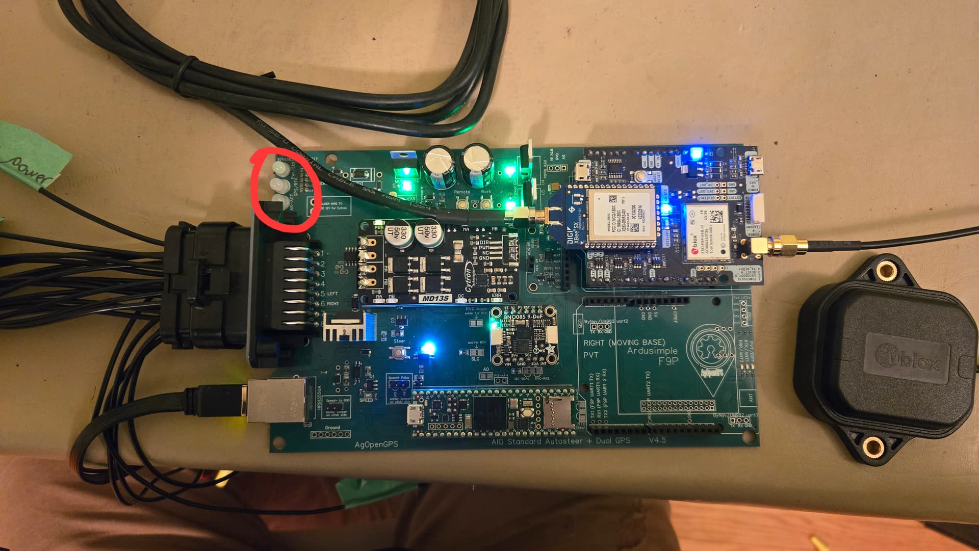
So I’ve got the board all put together now, but the 3 lights circled in red never light up and I’m not getting any gps response on AgIO. What am I doing wrong? I did flash the firmware on the f9p board and flashed the teensy as well.

Off the top of my head I would guess the teeny flashing didn’t take.

1 Like

Move your F9P to the other slot. It needs to be in right(moving base) for single

You do not get the orange light flashing on the teensy unless you get messages from f9p. F9p does not send messages if there is not enough satellite signal. Looking at your picture it seems you are inside the house, so place antenna outside the window, even better “under open sky” away from trees and buildings.

Did a flash on the teensy again, solved the problems. Must of done the wrong firmware the first time. Thanks a lot.

After flashing the teensy again, I got it all communicating with the F9P board on the left, however, I’ve moved it to the right now. Would it actually make a difference out in the field?

If you are using a single f9p it doesn’t matter what side it’s in.

1 Like

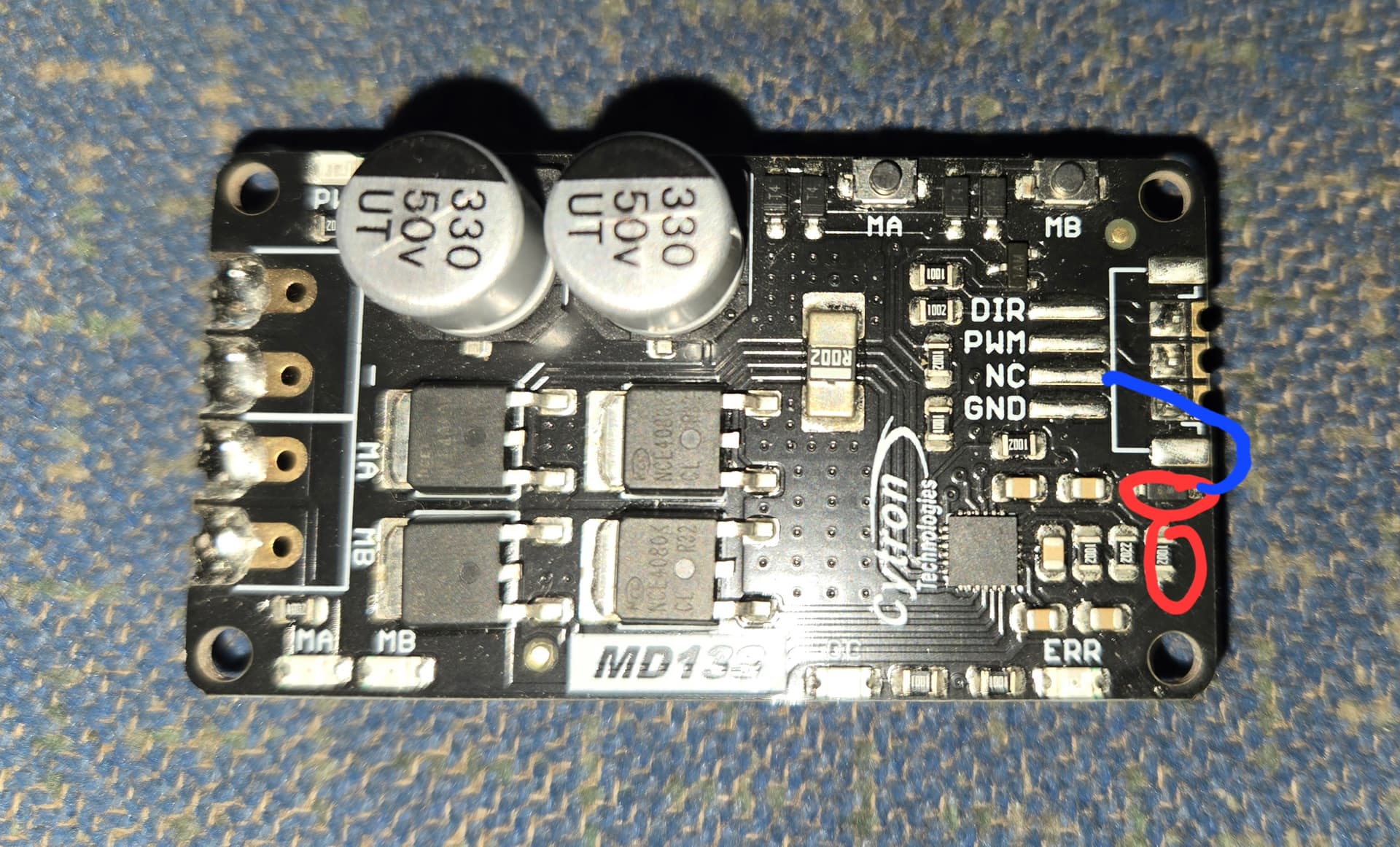
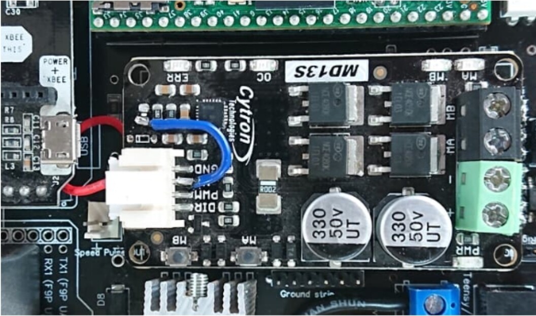
So to freewheel the motor, is this correct, remove the two in red and connect the the wire in blue like so?

Asking cause my cytron had a different connection on like the picture I’ve seen posted below. This is on a v4.5 board. If there’s a better method of freewheeling let me know, thanks

The picture on top is how I’ve always done it but either way will work. Make sure you have the wire what goes from the cytron to the board as well.

Which wire are you talking about…“from the cytron to the board”? I was only aware of the change in the image I sent you, then was going to plug it back into the headers on the pcb, am I missing something?