hello ag open community,
I have learned a lot over the last 2 weeks! There are great people on this forum! I’m so appreciative. Please read my post and point out anything that can help me. If nothing else you can laugh at my mistakes…
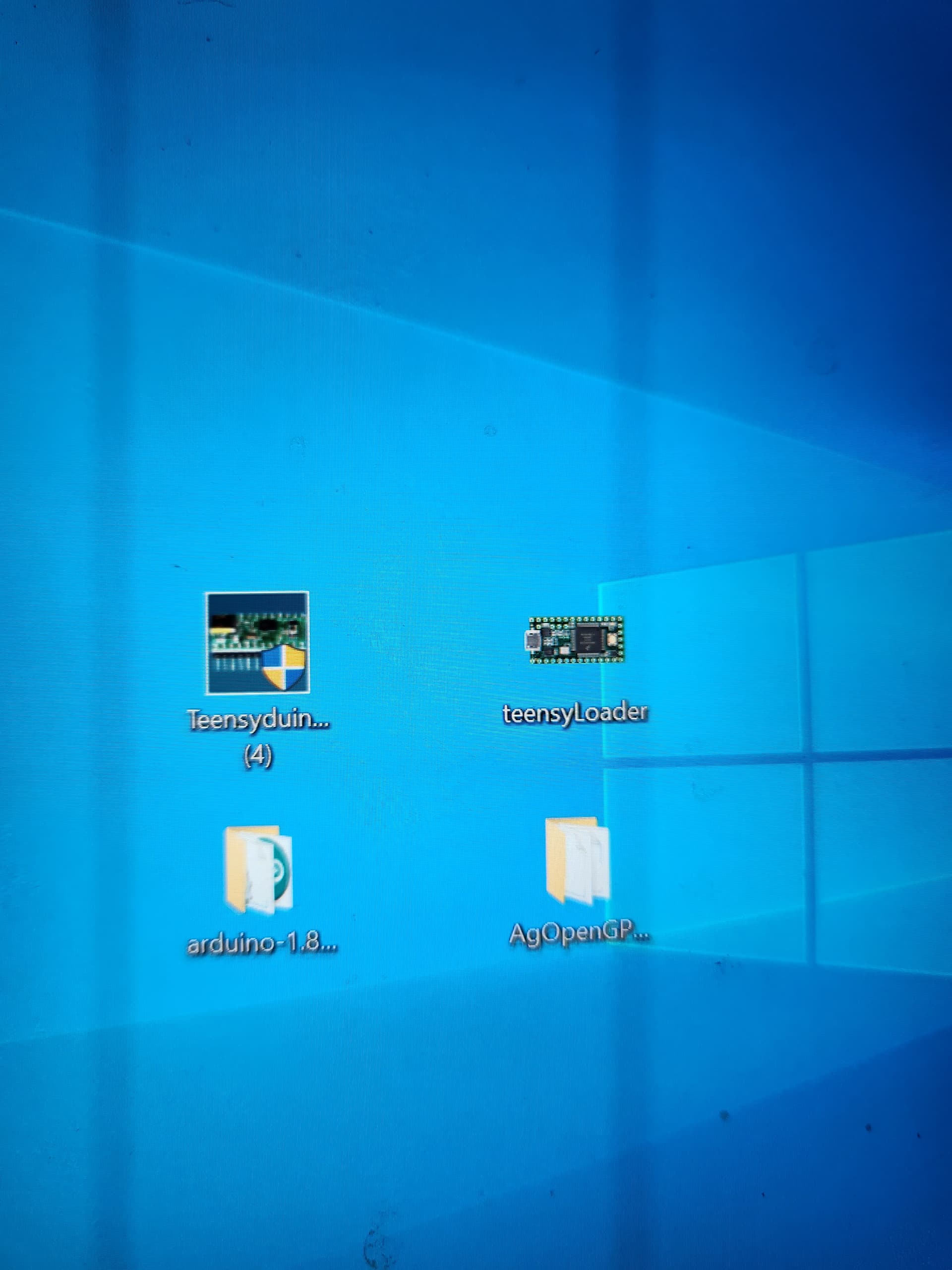
So I started out with a v2.4 board. Got the teensy 4.1 downloaded teensyLoader, then Arduino 1.8.1.9 then downloaded the ag open master file.
I followed the directions from the following page. (they were amazing and they worked!)
teensy 4.1 · farmerbriantee/AgOpenGPS_Boards Wiki · GitHub
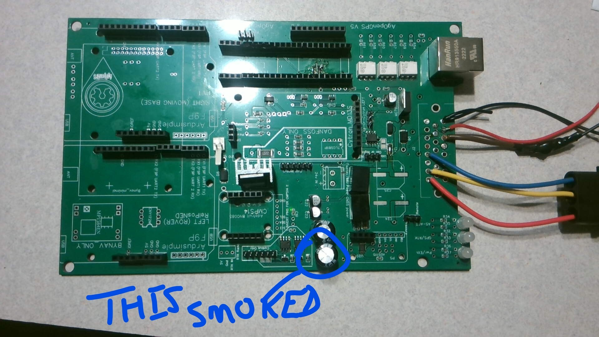
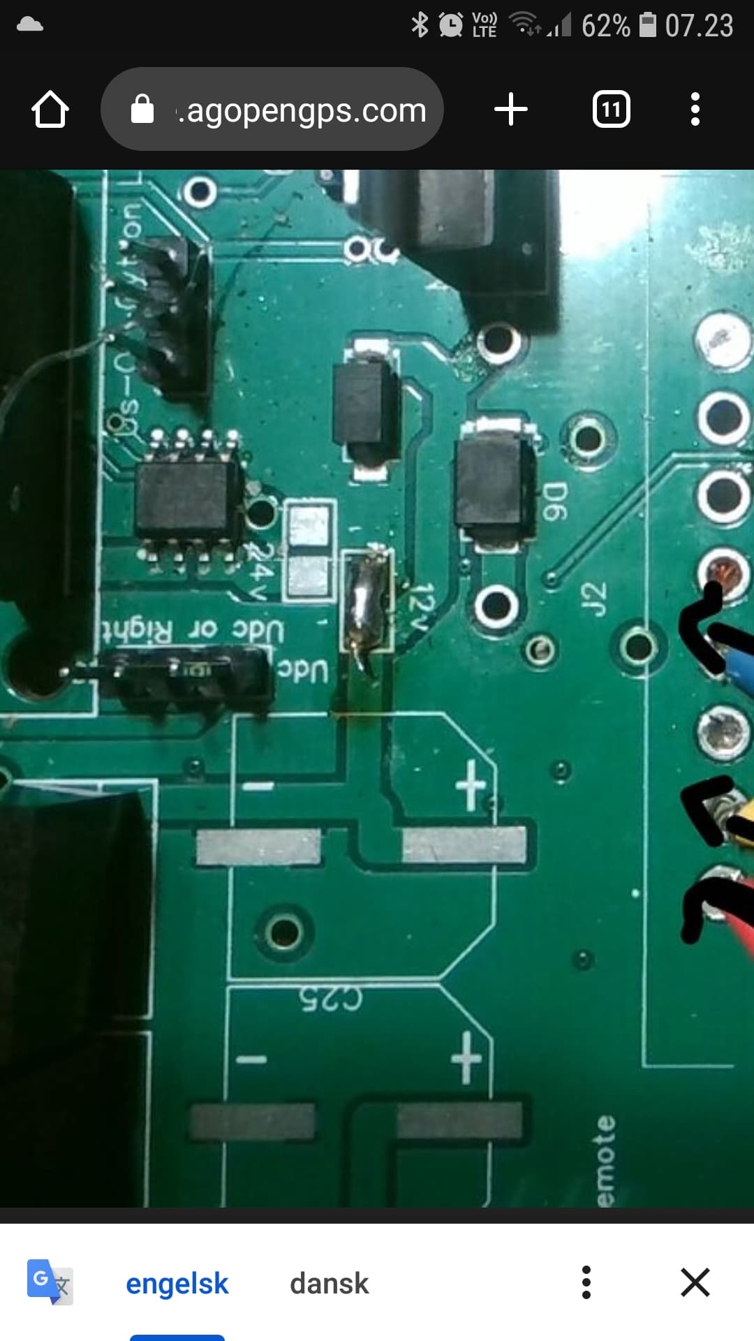
Then I hooked up my system. And I couldn’t get my ag open software to connect and the icon in the lower right hand corner stayed purple. I think I screwed up something in the wiring. I blew up my teensy and I blew up a capacitor. See picture…
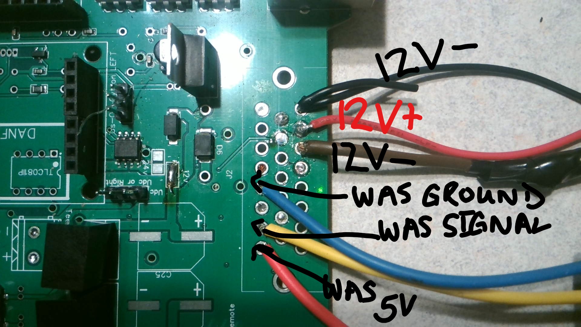
Here is a picture of how I wired it. Feel free to laugh but please give me some advice
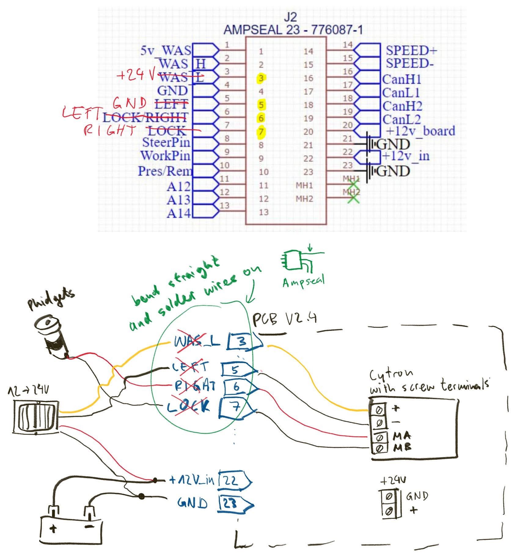
And I based my wiring off of this schematic
Please help me!
I don’t understand where the pins get wired too…and I didn’t buy an ampseal 23 pin connector I used another automotive connector…can somebody explain where I wire the following pins. Like, please tell me do they get 12v to battery or what they do…
Specifically tell me about…
Steer pin 8 where does that go? What get wired to it?
Work pin 9
Pressure/remote pin 10
Speed + pin 14
Speed- pin 15
+12v pin 20
+12v in
PLEASE HELP!! I’m really excited to do this project and I’m having so much fun! I don’t supposed anybody would be willing to set up a zoom meeting or video chat so that I could get some help in realtime?
Gnd on left pwm output is why??
Amd 24v on was low?
Maybe your problem is 24 back from md13s through current sensor and your soldered 12 v connection in center center of my screenshot.
Maube the capacitor was too cheap to survive 24 v? (Because you used the screw terminals on the md13s, and not the 24v in on AIO board which also would require to solder the 24v solder pads instead of the 12v solder pads you soldered)
But I don’t know if current sensor is allowing current both ways, and I don’t even have an AIO board.
Okay. So that wiring diagram is for running a 24v motor and requires the ampseal connector pins to be bent and then directly connected to the cytron motor driver instead of going through the AIO board. That is why none of it matches and you probably shouldn’t reference that diaghram.
Steer pin 8- Is for an external switch to engage steering.
Work pin 9- Used for implement work sensors so AOG knows when the implement is down.
Pres pin 10- is for some hydraulic steering
Speed + and - are a speed pulse output often used for rate controlers, etc.
12v pin 20- is 12v output from the board.
12v in- is 12v for the board.
It looks like you had everything wired up correctly. Are you running 24v anywhere? Usually the only time those caps blow is when they are overvoltage or exposed to reverse polarity. The only place 24v should be connected on the AIO board is to the screw terminals and cytron, not the ampseal connections.
I believe you are right about his correct wiring.
So yes J could measure if he has 24 v on the board at the capacitors. Actually the voltage regulators should survive 24 v, so you can still measure 3.3 and 5v on the board. Do the test without teensy or f9p and bno085.
Double check you have 24v correct polarity
Some of the Ampseal holes appear to have solder in them, have you soldered more wires on the reverse of the board?
Did you cut the surplus legs of the capacitors off after soldering?
Perhaps they have touched on the other side of the board.
Talking about capacitors. Did he connect both correct. White stripe with negative sign to GND?
1 Like