Hmm? Don´t know where you got that picture, although I think I have seen it long time ago.
In the original schematics still to be found DEEP under PCB in support folder, you find connections on ADS 1115,
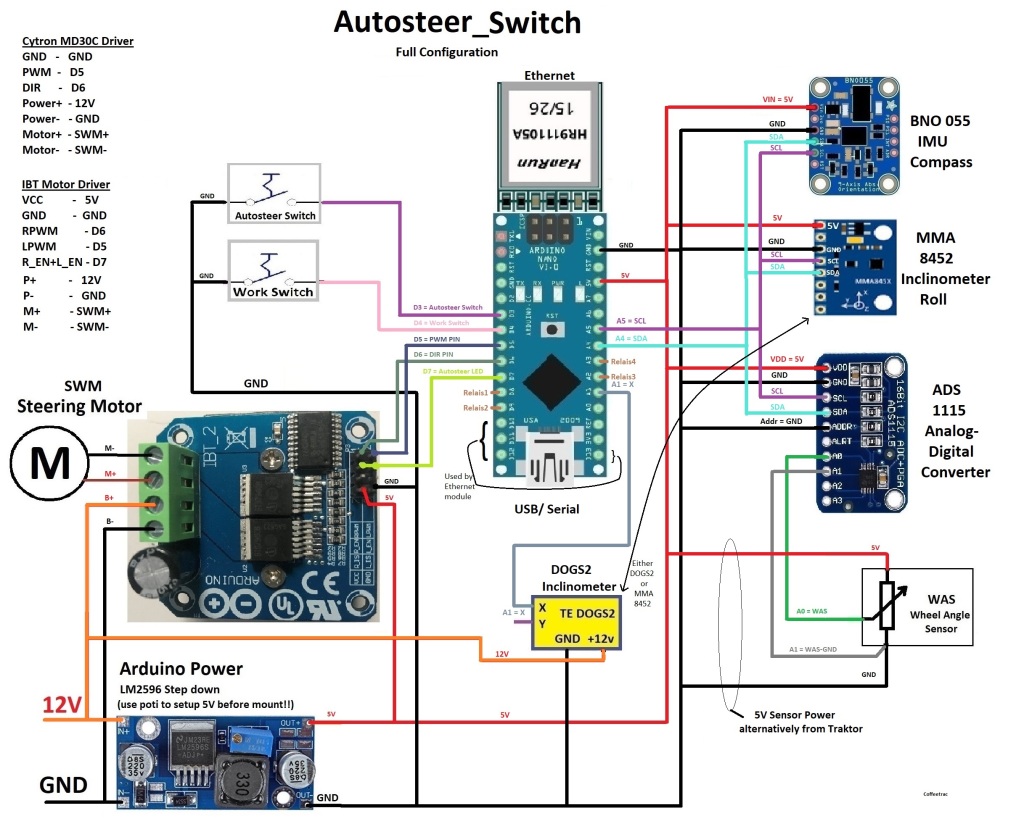
In the connection plan for CNH T6/175 we did not use any GND from the original WAS to AOG pcbv2, just a Y splitter of Signal wire. I used the common GND on tractor because the WAS is still used by tractor system. (This way it does still work perfectly)
Honestly the correct way would be to take the GND at the WAS and connect to LOW (Low is A1 on the ADS1115) at PCB (because WAS is still used by original tractor system)
When using the Low (A1) you should eliminate, if there were any voltage difference between common GND and GND at the WAS.
Your picture does indicate that the part you show is a factory installed WAS alternatively with power from tractor.
Do you have wiring for newest version, but for motor i use nano, and for gps i’m planing panda.
I do not have pcb, but i will make it.
For testing i will connect it with wires.
It can be quite a bit more difficult to get started if your wiring things together yourself and have problems. I started like that and found using a PCB is much better.
I also started with those schematics. They make AOG accessible for table test at very low cost. Thing is when you go for PCB you can’t order under 5 and it is best to order components for all 5 for shipping costs. So cheap breadboard test to understand how it works before you go for PCB is great.
You do not need dogs2 or any IMU for testing. The BNO will be used together with Teensy (the panda setup).
I still use IBT but, most others use MD13s, as it fit on some of the PCB.
For testing you can go with Nano powered by USB, an ADS1115 with a potentiometer as WAS.
The PWM can be measured with multimeter at the correct pinouts (see INO)
You see latest pinout and other explanations in the INO (Autosteer_USB_v5_0) in the support folder, so yes the wiring has changed. (part of ino below)
The A0 mentioned in ino is the one on Nano not on the ADS1115
//Dir1 for Cytron Dir, Both L and R enable for IBT2 #define DIR1_RL_ENABLE 4 //PD4
//PWM1 for Cytron PWM, Left PWM for IBT2 #define PWM1_LPWM 3 //PD3
//Not Connected for Cytron, Right PWM for IBT2 #define PWM2_RPWM 9 //D9
As it say enable ibt_2 , so connect to both L_EN and R_EN
Oh you got it, and yes the d4 goes high when autosteer is on, and remember go faster than min speed set in AOG or use the manual steering in steer settings.
BOTH autosteer icons at bottom right in AOG must be green.