In your photo,
Blue cable is signal
Brown is 5V
Green/yellow is GRD
Is this how you have it wired?
In your photo,
Blue cable is signal
Brown is 5V
Green/yellow is GRD
Is this how you have it wired?
Agree with buying the correct connector, this is the correct one:
Is the track the inside of the tires, the centers or the outside? Right now it’s measured from center to center. And how do you figure with duals? I just used the center of the inside tire. And yes, I rechecked all the measurements. It’s a new style JD7520, so it’s small frame and quite a short wheel base.
I I’ve tried switching the motor off in the middle of a U-turn and seeing how close it is. It has it turned almost to the stops, but not forced against them. So I think the max steer angle is really close.
I believe they’re at original.
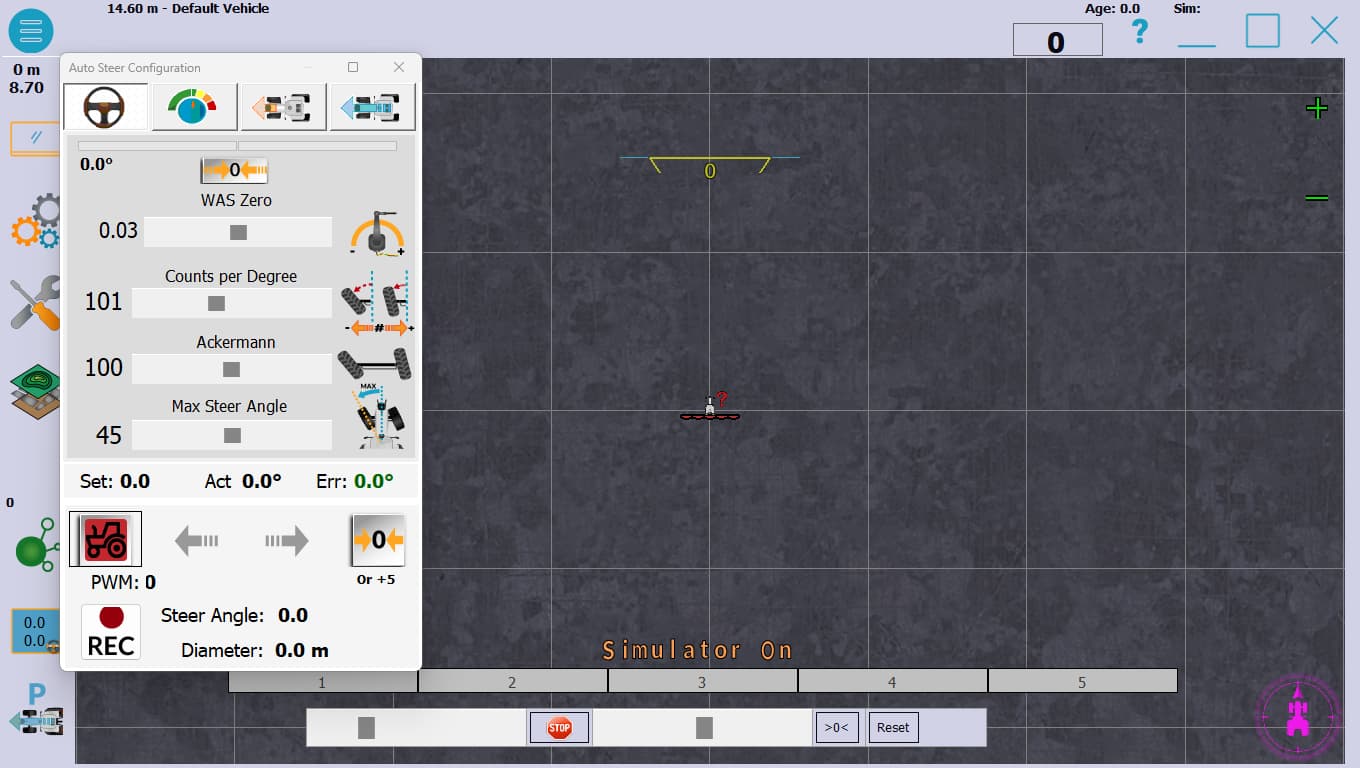
What is the diameter vaule in a rec funcion?, try close max steer angle
Center of first tyre is the measurement
11.54 m
25.6°
Put in radius value 11.54/2, and try it, try Look Ahead 2-3
Do I use 11.54 m? I was thinking I’m supposed to use 1154 cm/2.
yes in cm
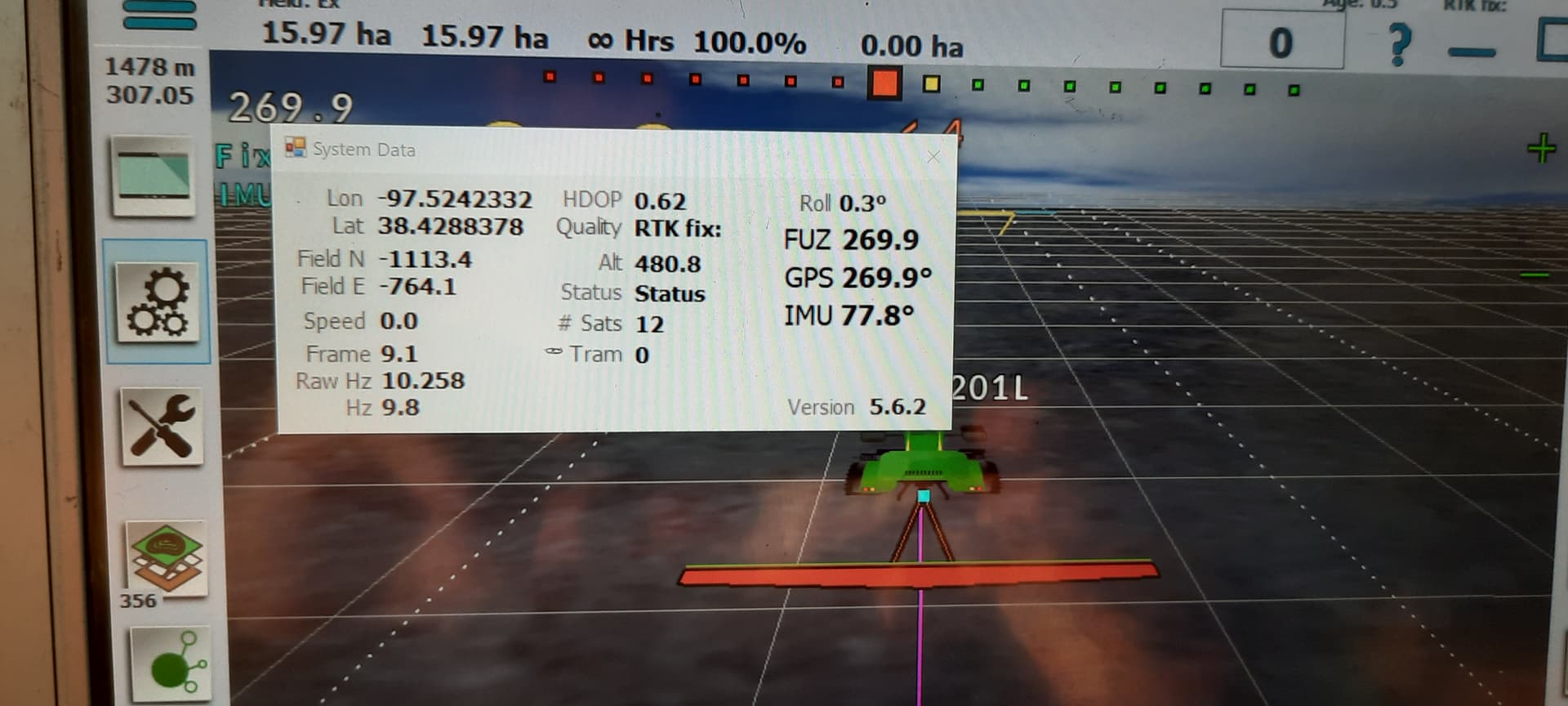
@CCW have you checked what your gps is putting out for hertz like @PotatoFarmer mentioned earlier. I had the same exact problem. Certain things seemed to help, then all over again steering side to side. The @Aortner configuration loaded at 10 hertz but came up on gps at 1 hertz. Chased this down from help from the brains here and found it was still only 5 hertz. Finally got it loaded at 10 hertz and completely straightened out the steering! Click on the speedometer box on top right of your gps screen and see what the hertz is. It should be 10~?.? This is found right below the FUZ, GPS and IMU readings.
I did a bunch of experimenting this afternoon to see if I could set my antenna correctly at +55: longer wheelbase, shorter wheelbase, lower CPD, reverse the direction of the IMU, invert IMU, invert motor direction. Everything is very unstable until I go back to -55.
I also tried switching to metric. All the settings seemed correct whether in metric or customary, so I don’t think it is an issue with not converting correctly.
I tried adjusting turn compensation, but didn’t seem to help, so I went back to default.
It never really turns away from the line until it’s too late unless set at -55. Is there any other setting that would affect that? I have tried to process in my mind what it is doing at at -55 versus +55 and figure out what other setting would do the same thing.
Have you by any chance, chosen the combine icon for tractor. Settings for combiner are like tractor in reverse.
Muchas gracias por vuestras ideas.
Creo que he empezado a encontrar la solución.
Resulta que yo unas veces establecía el 0º con la PCB conectada y otras no. Pues bien, de estar conectada a no estarlo cambia la Vcc de +5V a +4,6V. Por eso me daban resultados raros.
He empleado horas en descubrir esto, tenedlo en cuenta y no las perdáis vosotros.
Thank you so much for your help
I think I’ve begun to finf the solution.
The trouble was that sometimes I setted the 0º of the WAS with the PCB turned on and sometimes with it turned off. The voltage supply varays from 5 V up to 4,6 V. That’s why it gives me erratic outputs.
I’ve spent lots of hours until getting this. Take this advise into account
I don’t think, because it is showing a tractor on the screen, but I’ll check.
I want to adjust the linkage on my WAS so it is closer to center. That way my WAS center can stay close to zero. Then i want to look into my CPD a little more and see if I can figure anything out there.
Make sure your WAS is centered with the wheels straight. Then adjust your linkage arm for close to full stroke of the sensor. Your cpd is important more so than anything to get set correctly.
I think we narrowed it down to something in our Panda. If we unhook the ethernet and plug straight into the ardusimple receiver usb, it works fine with the antenna set correctly. Now we need to figure out if it is in the receiver configuration or in the Teensy configuration.
Which teensy file is correct for 5.6.2?
And is the Ortner file supposed to work as is? For some reason AOG would not connect with Panda module until i changed a few settings in the Ortner file. I can’t exactly remember which, but I think it was something in UART2.
I THINK I got it. I got to wondering if at some point I had accidentally overwritten the Ortner file. So I found the file on here and ran that through U-Center. It looks like it is all working now. I can set the antenna correctly and it finds the line okay. It was too late in the day to do much testing, but it seemed like it was acting correct. It followed very well over a terrace at an angle. Then I went in reverse and it went right back over the terrace in the same tracks. I will do some more testing and report back.
Actually a very simple fix, but I spent numerous weeks wasting my time trying to fine-tune settings. And did most of our wheat planting with markers, but at least it looks encouraging.
It makes me really curious which settings in my receiver were actually wrong, because it worked reasonably well over USB.
Thanks again for all the input.
It works. Keeps at 0 in a lot of the time, I see 2 in very rarely.
Thanks again for all the time and effort