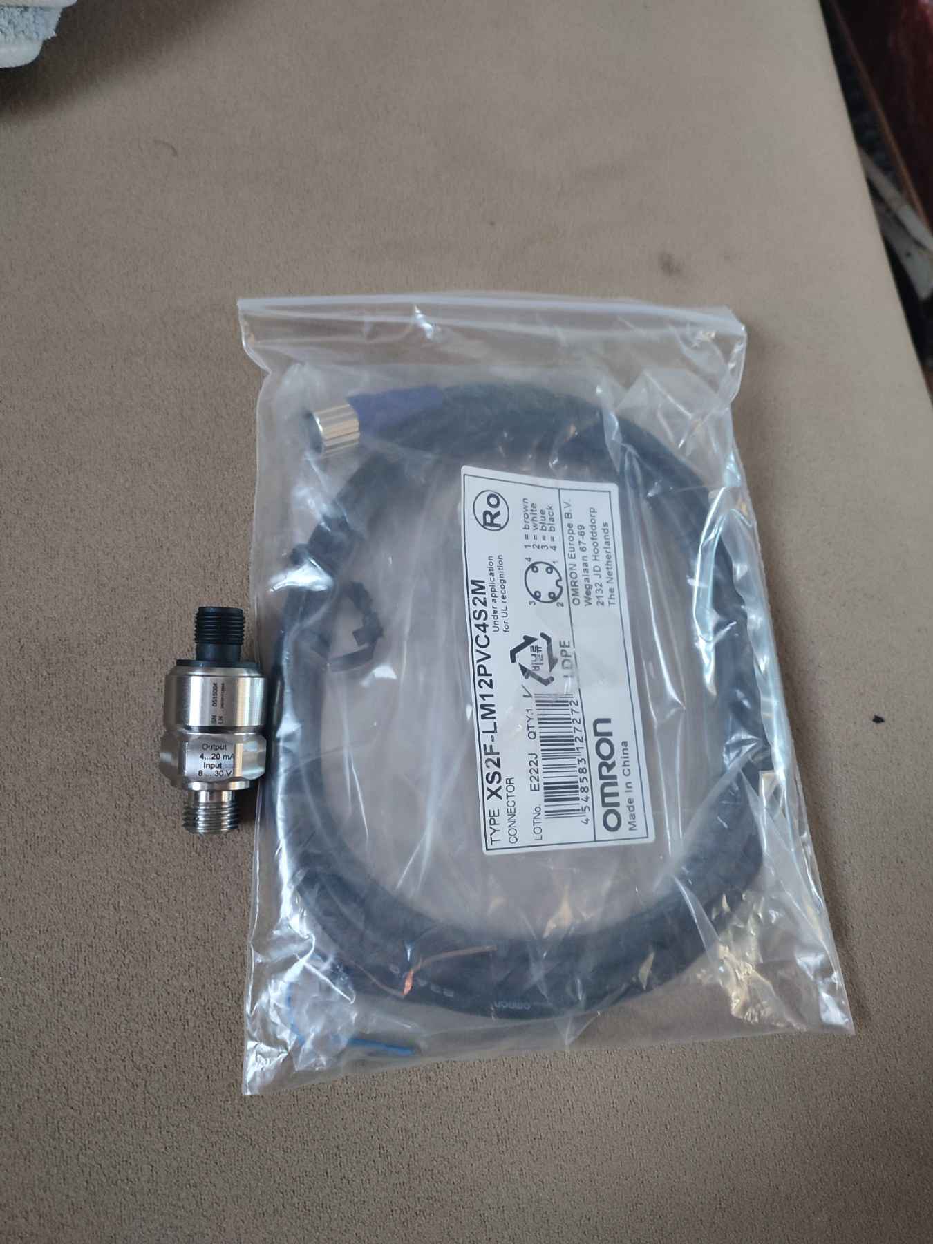
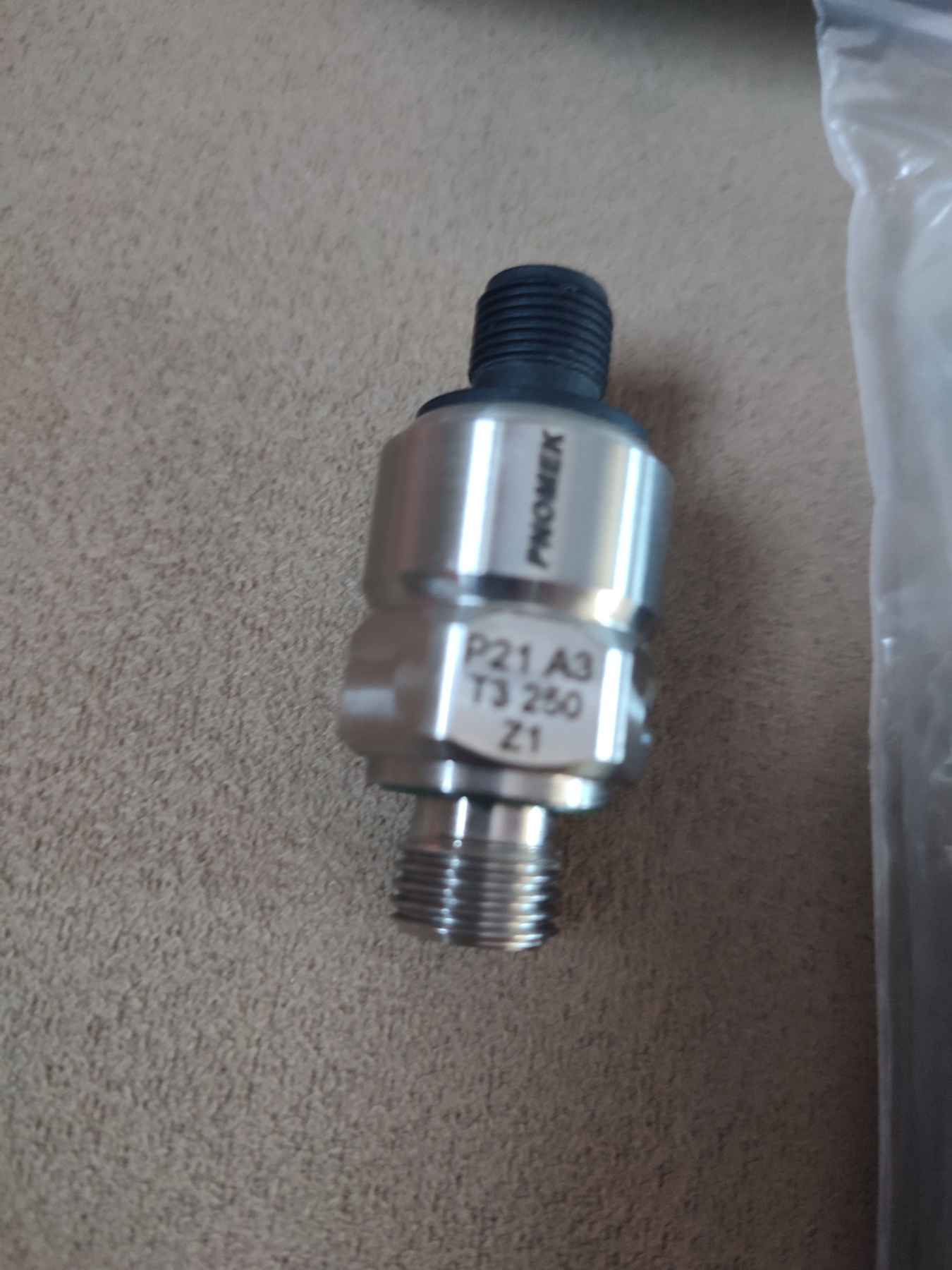
I have an old klaas mega 204 from 2000. It used to have a factory solution for controlling the height of the cut of plants, but it does not work after years and lack of maintenance. I would like to make such a system on an arduino mega 2560 v3 using 3 sensor potentiometers for installation on the bottom of the header, connected to the ski copiers and a pressure sensor in the hydraulic system (Придбати Реле тиску P21 A3 T3 250 Z1 (0-250 Бар) з доставкою по Україні. Найбільший оптовий склад компонентів гідравліки "ГІДРО-ГІД")pnomex p 21 a3 t3 250 z1output4…20mA input 8…30v at 250 bar the system should be a copy of the John Deere S770, for example, read from 3 position sensors and control the electro-hydraulic distributor, controlling the height and angle of rotation of the header (so as not to rake the soil into the header and mow as low as possible), also monitor the pressure in the hydraulic system so that the header easily travels over the soil but is not too heavy to rake the soil as well as in John Deere, have the ability to adjust the reaction speed and set the cutting height and select operating modes (this will be relevant for old combines), who can help with this issue, thank you very much for your cooperation
for example, video of system calibration
(https://www.youtube.com/watch?v=qWLiDZ3lhtI&ab_channel=CastongiaTractor)
This will ensure the same cutting height of the plants by the header and minimize grain losses in automatic mode.


-
- Header position (height)Description: The system controls the height of the header above the ground to avoid damage to plants or loss of crop. Settings: Height of lifting/lowering. Sensitivity to uneven ground (automatic height adjustment). Implementation: Position sensors (potentiometers or incremental encoders) and hydraulic cylinders are used.
-
Header tilt angle (forward/backward)Description: The angle of the header affects the harvesting efficiency, especially in uneven fields or when working with different crops. Settings: Forward or backward tilt angle. Automatic angle adjustment depending on the terrain. Implementation: Hydraulic cylinders and angle sensors are used.
-
Header rotation angle (left/right)Description: The system allows you to adjust the header rotation angle to accurately follow the field contour. Settings: Left/right rotation angle. Response speed to direction changes. Implementation: Hydraulic cylinders and position sensors are used.
-
System response speedDescription: Determines how quickly the system reacts to changes in the header position. Settings: Raise/lower speed. Speed of change in tilt and rotation angle. Implementation: Regulated via the fluid supply rate in the hydraulic system (e.g. using proportional valves).
-
Ground sensitivityDescription: The system automatically adjusts the header position depending on the field contour. Settings: Level of sensitivity to irregularities. Response speed to changes in the terrain. Implementation: Height sensors (ultrasonic, laser or mechanical) are used.
-
[19:46]
-
Header widthDescription: For headers with adjustable width, the system monitors the position of the sections. Settings: Cover width. Position of the outer sections. Implementation: Hydraulic cylinders and position sensors are used.
-
Operating modesDescription: The system has different operating modes for different harvesting conditions. Settings: Field mode (standard). Transport mode (header raised). Precision harvesting mode (for difficult conditions). Implementation: Software with the ability to select modes.
-
Overload protectionDescription: The system protects the header from damage when it collides with obstacles. Settings: Overload sensitivity level. Overload response speed. Implementation: Load sensors and software protection are used.
-
Integration with the combine control systemDescription: The header control system is integrated with the general combine control system (for example, John Deere GreenStar). Settings: Display of parameters on the main display. Automatic control depending on the speed of the combine. Implementation: CAN bus and software are used.
-
CalibrationDescription: The system requires periodic calibration to ensure accuracy. Settings: Calibration of position sensors. Calibration of hydraulic cylinders. Implementation: Special calibration procedures are used.
-
[19:46]
If you want to implement a similar system, start with basic functions (position, tilt angle, rotation angle), and then add more complex functions, such as automatic height adjustment or integration with other combine systems.

Hello, i was thinking about similar project, why did you want to use hydraulic preassure sensor?
for the mode when you need to mow as low as possible, but so that the ground does not rot, this can be achieved only when the pressure of the harvester on the soil is known and this parameter is controlled automatically


So you want to control the height of the cutter bar in 2 modes (ground contact and height control), the John Deere system uses 3 encoders that are also used for the WAS on John Deere tractors (one for each end of the head and one for the middle). The middle sets the absolute height and each end control the head tilt side to side, this is one system, no hydraulic pressure or whatsoever. The crude system used on older combines are three reed switches instead of hall sensors.
The Hydraflex system that uses the hydraulic system is for contour of the cutter bar itself, not the header, it has hydraulic cylinders under the head that are set by the operator, letting it flex a bit, a lot or being rigid. The pressure sensor that you see on the header is for pressure feedback to the system and the operator (higher the pressure, stiffer the cutter bar).
And the rigid height mode (we use for wheat down here for only cutting the ears) works by using three longer skis on three contact points on the ground, but I don’t know 100% how it sets the height for the cutter head.
This mode works almost identically than flex mode. On your JD you also have a setting to run the table in rigid mode at a set ground pressure.
The combine open a pressure accumulator on the combine side to give a range on the header cylinder and the pressure sensor keep a defined pressure in it.
On a T670 in rigid mode I typically had button 1 on ground pressure, 2 on the feeler gauges and 3 the lift height.
Is there a similar system on Arduino?
Not as I know.
I’m running a Gleaner S77 now. These use on/off valves for the header activated by automotive relays in the cab.
I have seen that I can replace the cartridges with proportional ones directly (Hydraforce ones).
So my plan is to remove the relays, build a pcb with 6 potos, min and max pwm and ramp speed for both up and down.
Then just read the signal pins from the relay sockets and modulate the output and feed trough the relay pins.
For now I will keep the original header height controller, it works correctly with the ON-OFF valve, I hope it will be better with the valve mod.
So the sensor module would not be before 2026, for sure I must have good working proportional valves before.
I agree, the proportional valve will work more precisely and smoothly, but I have nothing to replace the valve on my mega 204
an ordinary valve with an electric drive probably will not work proportionally even if you give it portion control of an electromagnet
This topic was automatically closed 60 days after the last reply. New replies are no longer allowed.