I bought a set of V2.4 Standard boards from the forum and was doing some pre testing and fitment and believe the board may not be assembled correct.
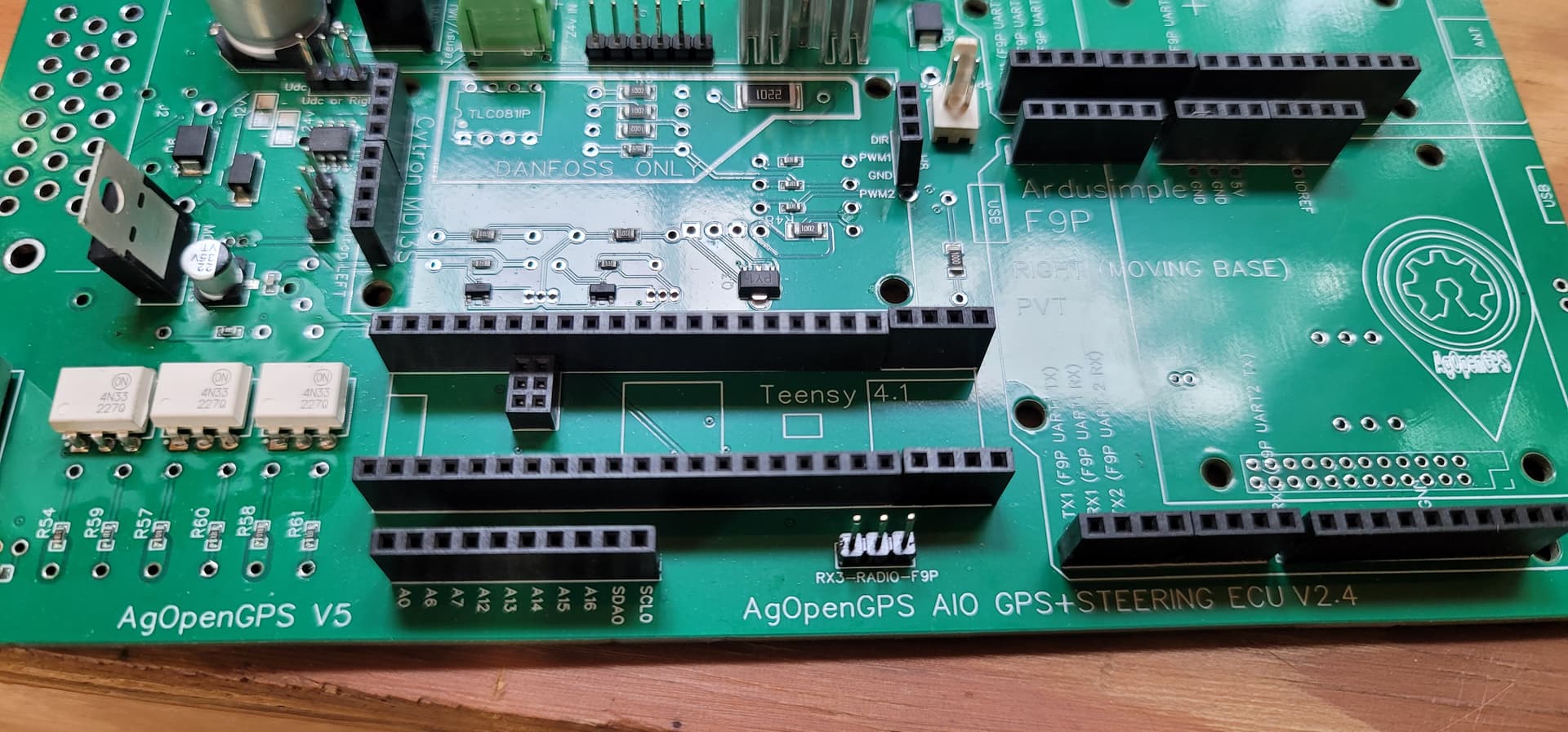
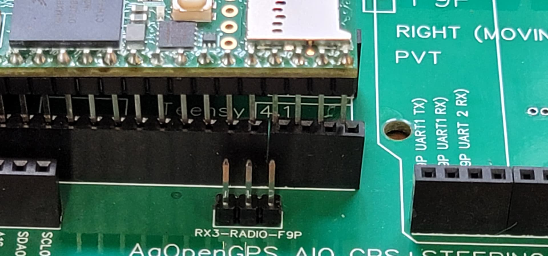
I attached a couple of pictures, the four pin female headers on the right side are a different size and seem to have different offsets. All 5 of my boards look the same, what’s normal…?
They are assembled correctly. Those are the 20+4 headers and they are a pain in the ass. You will probably have to pull off the plastic from the small header and file it down. There were some instructions in the AIO discussion
It was how it was done for parts availability. All of the V4 boards now have the option for the 24 pin header. You don’t have to take the whole header off and replace it. It is much easier to just pull off the 4 pin header and file it down.
Did you find a solution for longer ethernet pins? I’m considering soldering a 2x3 female socket to the bottom of my teensy, then putting the male pins into it and basically sandwiching them in between this and the female socket on the pcb. It looks like it will get things to the corrrect height(or very close). It is on a panda board, not sure if this is a good solution or not.
I am not sure one could put a Teensy with the Ethernet pins on the bottom into a breadboard. The Ethernet pins would line up with pins 20 & 21. My breadboards have a busses going side to side which would short all the pins together.