I thought I’d share a bit of detail on how I made my steering motor work along with a video of it all working. My remit was to not impact too much on the tractors internal appearance, not to obscure existing controls or displays, be very easy to completely remove, relatively quiet and 100% safe.
If admins would prefer this split into two separate posts in different sections please say.
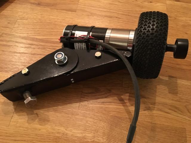
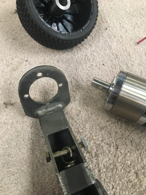
The motor I used. I was advised it was a bit slow, but when used with a 115mm diameter wheel, it doesn’t seem to be a problem.
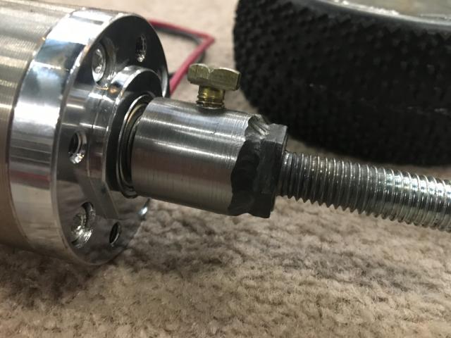
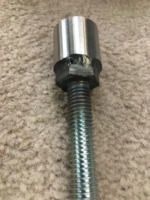
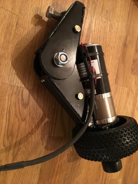
…and the simple boss constructed to drive the 1/8 scale RC buggy wheel.
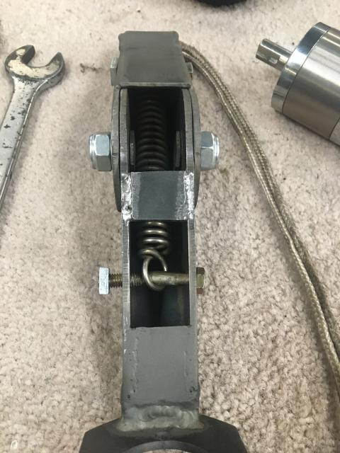
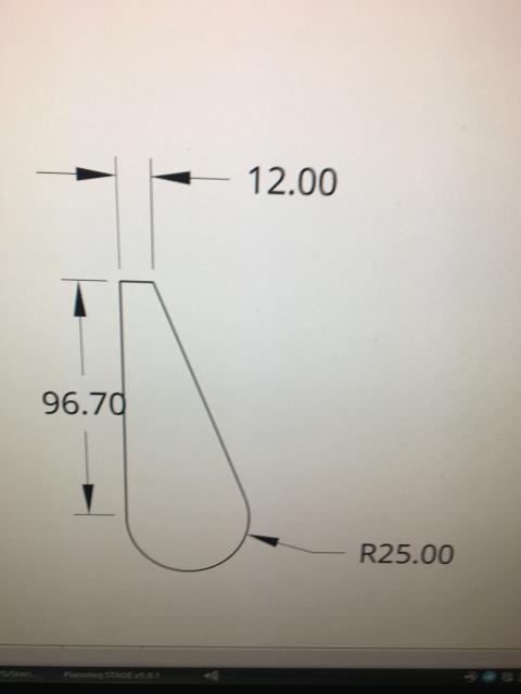
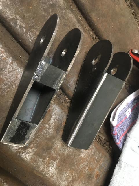
The bracket itself is made out of 4 identical plates welded together to make two interconnecting arms. The dimensions are rough.
!
A microswitch (out of an old HP printer) is fitted inside to operate AOG’s steer switch.

A spring inside creates the ‘over centre’ nature of the mechanism. The bolts holding it together have their heads machined down to give the spring room to move and the spring retaining bolts are bent slightly to keep the spring central in the mechanism.
The finished mechanism, showing the 10mm metric fine bolt that retains the thing to the lug on the column.
…and the lug i welded to the steering column.
My test circuit board, built on stripboard. BNO055 on its own away from other things!
Finally, a short video of it working. A bit jumpy because I’d forgotten to enable the MMA and BNO in the settings, but it works surprisingly well, considering how rough the field is and I’ve not done much in the way of setting up yet.
9 Likes
Excellent, we used the same motor as you but we plugged it directly into a JOHN DEERE bracket, it is a good motor, silent, and that we can easily turn without electricity
1 Like
This is the basic action of the bracket. There is a bearing on the end of the shaft on the finished mechanism allowing you to push it out of action without having to hold a moving part, but negating the need for a separate handle.
4 Likes
I realize this is an old post, but being nearly fatally optimistic, here goes. I am an “engineering challenged” farmer so I need further explanation of exactly where the over center spring is attached within this hinge. I am working on a John Deere 5101EN installation and this motor engaging hinge would fit in my small tractor. Diagrams/photos of the spring placement would be wonderful. I see that older automotive clutches have a similar setup to hold the clutch pedal in the engaged position. What is the correct term for such a hinge, so I can at least Google my way out of the darkness of my ignorance…lol Thanks for any and all help that can be provided.
Simon_1…Thanks for the response. What I am after is the placement of the 2 bolts that have a slight bend in their centers to keep the spring in the center of the channel on this design. It appears there is only a small amount of travel from the engaged position to the disengaged position (less than 45 degrees). I am currently trying to reverse engineer this from drawings. Then possibly trial and error to figure out correct bolt placement.
Have you tried to make a drawing of this, either to show us or for yourself to understand the application?
Hi. The spring is connected between the through bolts that you can see at the narrower ends of the mechanism. The large bolt in the middle doesn’t go right through. It is two bolts with their heads machined right down to make them shallow, allowing the spring to pass between them. This produces the over centre. As can be seen in the pictures posted a few posts before this video.
The mechanism has worked flawlessly for over 3 years.
2 Likes
thanks…i am in the process of building one and i am sure it will all be crystal clear as my proto type taes shape…lol.really glad to hear it has worked so well…thanks again for the input
To help assemble it i put a piece of threaded rod through the big holes and used nuts to position the sides at the correct distance. Made welding it together quite easy.
The dimensions above are only approximate and think my finished article turned out slightly larger.
I wanted something good and solid that didn’t obscure existing controls and could be removed almost completely very easily.
When cutting the pieces that dictate the width, remember you need to be able to get the second bolt in between the insides and the first bolt to fit it. Basically the inside measurement of the whole mechanism needs to be at least as wide as the total length of one bolt plus an additional bolt head. If that makes any sense. As I said, machine down the bolt heads as thin as you dare whilst still retaining some strength and ability to hold them with a spanner. Also the bolts obviously need to be long enough that a locking nut will hold on it.
This view shows the area I’m talking about and how the bolts fit. You can just see the machined down hex heads in the centre of the mechanism.
The bend in the spring mounting bolt is intentional. It stops the spring working it’s way to either side then rubbing on the centre pivot bolts.
Thanks so much for this info…currently learning how to use freecad before moving back into my shop…not as much fun as it sounds like, but ya gotta start somewhere…thanks again, from currently foggy Central California lol
…
For quick simple design I find LibreCad as easy as most.
Works on most platforms I think. I use Linux apart from having to use windows for AOG unfortunately.


")