So out of desperation to get something done. Having no luck getting anything UDP to work like it should I am trying to get 3 sections to work on with a usb machine board. This is still AOG version 6.2 and Machine_USB v5 for the Nano. The way I think I understand it is that I should hook my sections to pin 13 for section 1, pin 5 for section 2, and pin 6 for section 3. I can’t for the life of me get pin 13 to do anything. I can put in 4 sections, make section 1 width 0 and hook to 5,6,7 and get my three relays to work. Any ideas? Thanks for looking.
The pin out is a nightmare to start but actually makes more sense when you get it to work.
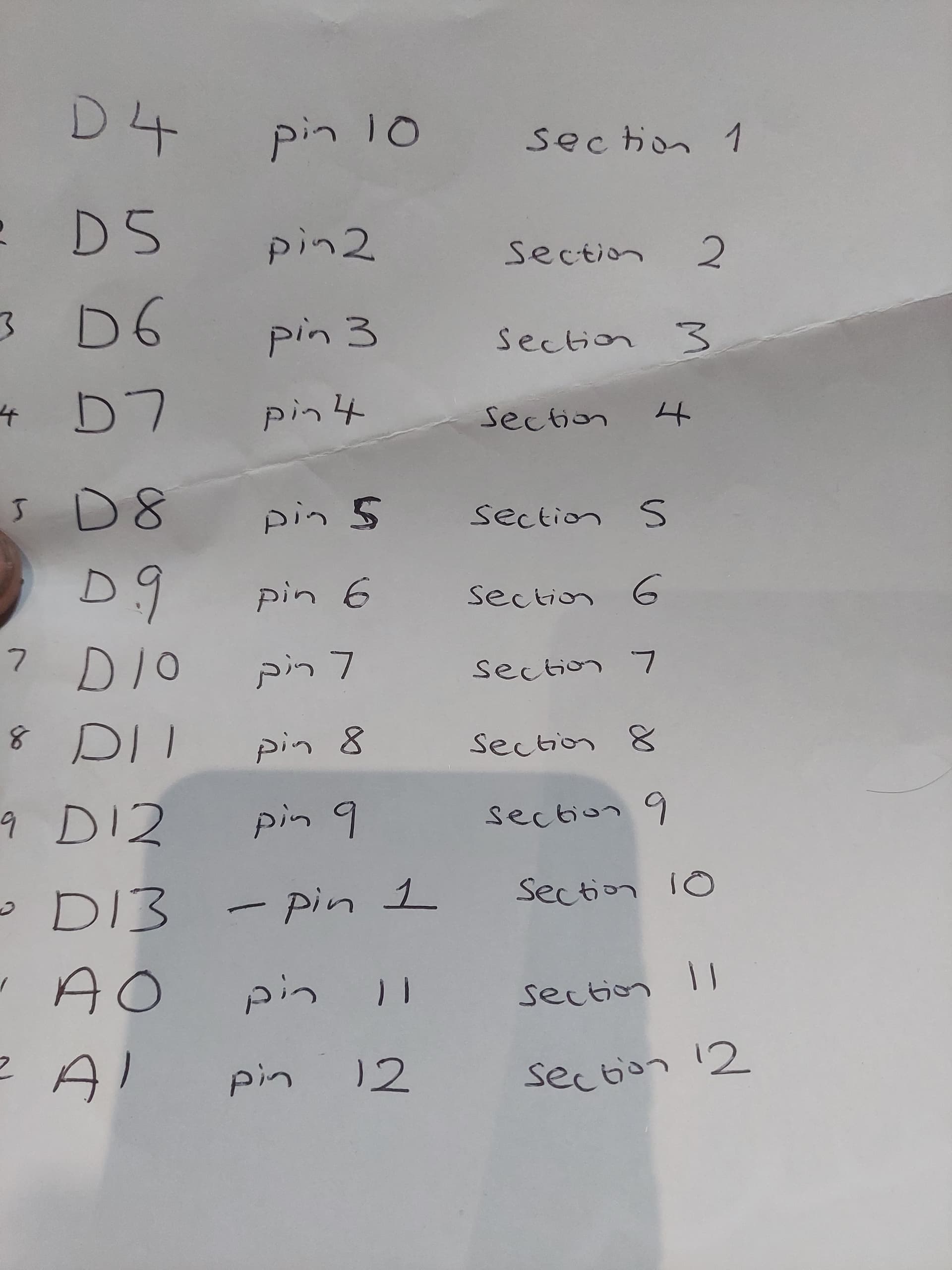
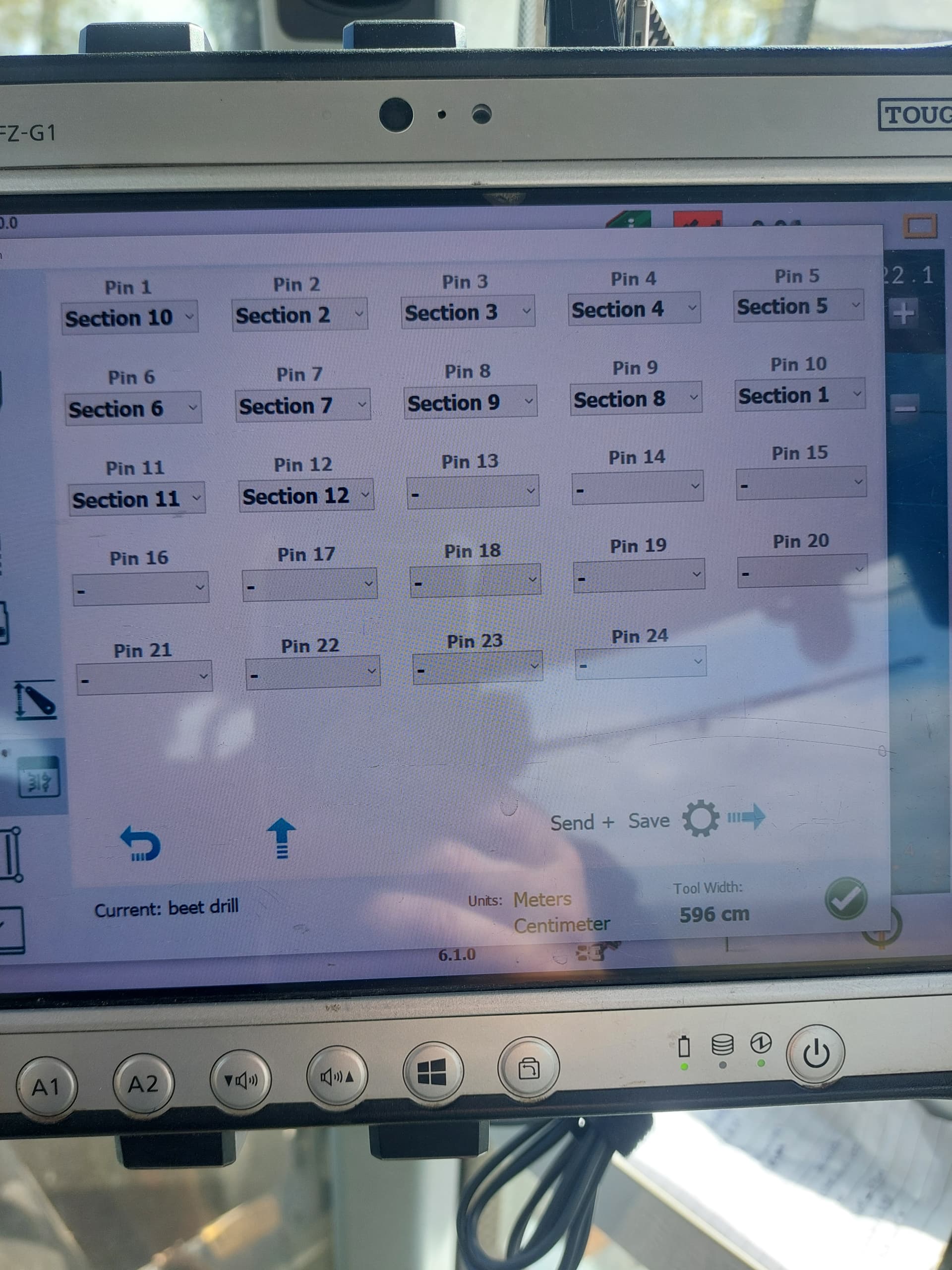
This is my pin out for 12 sections.
This is tge standard configuration
Hope this helps
3 Likes
First and foremost, Thank You. It now works. Not sure how I would have figured that out on my own. I thought I had read every post imaginable but still hadn’t gotten it. Hopefully someday I will be able to look at the ino and figure it out on my own but right now it seems that’s not the case. Where and how did you find the information? Once again Thanks.
I had a lot of trouble getting UDP working with a nano both for section control and for the RC12 rate control module. I bought a 3 pack of nano Ethernet shields. None of them worked. I still don’t know if the shield I bought had a different pin configuration, or if all 3 were bad. I bought another brand of Ethernet shield and it connected right away.
1 Like
So where did you finally wind up getting your shields. I have had a couple batches and haven’t gotten one that would work yet. I would really like to do UDP but can’t seem to find the right combination of parts. Seems all I should have to do is plug the NANO into the shield, load the UDP Machine ino and it should be found. Never has yet and I’m not experienced enough to figure out why.
Check where the CS Pin of your shield is connected to nano:
If it’s not Nano pin 10, so you have to change within the .ino
    //ethercard 10,11,12,13 Nano = 10 depending how CS of ENC28J60 is Connected
    #define CS_Pin 10

    /*
    * Functions as below assigned to pins
I can’t find any documentation from the manufacturer of my shield to do that. What method would I use other than that to check what pin is the CS pin.