There is no axle in my vehicle, the front 2 wheels are self-powered and I have to do the steering with 2 separate dc motors, can I connect (2 pcs)was sensors to the front 2 wheels separately? If I can connect it, can I attach 2 WAS to the ADS on my panda card or do I need to use 2 ADS, if you show me no, I would appreciate it.
Best regards.
What is your vehicle? There is probably a better way to read the steering angle.
Hello Buckwheat;
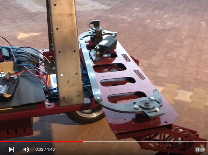
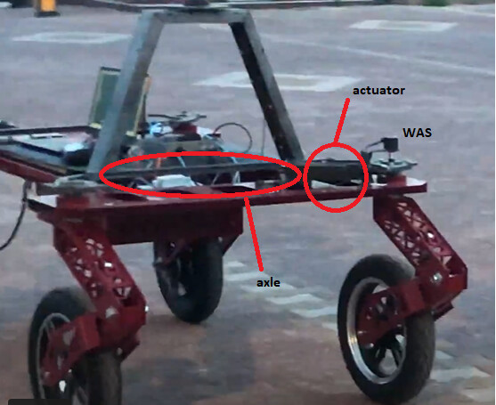
This was my prototype vehicle, but I made it more advanced and my new vehicle will no longer have axles and will be driven by 2 separate actuators on the front 2 wheels. As you can see in the photo, there is 1 WAS and 1 actuator.
1 Like
Hello whiterose,
I see a few different options:
The two wheels must be slaved together in somehow? As long as there is a “linkage” between the two wheels - it doesn’t have to be a steel linkage, it can be a software linkage - then you can just use a single WAS on one of the wheels. Use the zero and CPD and ackerman settings as normal.
Your controller must have some kind of steering angle setpoint? Can you communicate that setpoint to the AOG controller somehow? Then you don’t need a sensor at all. Is the vehicle remote control? You can read the 2mS PWM signals from an RC receiver using an arduino/teensy pi using the pulseIn() command.
1 Like
My vehicle is following the road registered with AOG, I have already made the RC control receiver as you said, thank you.
But in my new vehicle there will be no connection between the 2 wheels, the left wheel will be driven by the left actuator and the right wheel will be driven by the right actuator, if I only attach the was sensor to the left, I cannot know the angle of the right wheel exactly, the position information of the 2 actuators will be simultaneously.
i need to get it. I think I need to do it like this (using 2 WAS) to connect the feed wires of the actuator connected to the left wheel and the right wheel, and I think I can solve the WAS sensors that I connected to both actuators by modifying the code, your ideas are valuable to me.
If you want to do use separate WAS sensors then you could connect one WAS to the AIO board WAS_H, one to WAS_L, and write a few lines of code to average the readings. Both WAS_H and WAS_L are separate analog readings. That would be a nice and tidy installation, you won’t have to change the AIO board or make any external circuit.
I think you can probably do it all with one WAS, since the wheels will steer together, but two WAS and a few lines of code will definitely work too.
1 Like
Does that mean there are internal potentiometers in the actuators? If so then you have the was inside already. I suppose you have programmed motordriver to read actuators so both wheels will point in same direction
1 Like
Dear Buckhwheat;
Actually, this is exactly my purpose, so I want to use both was_h and was_l using 1 ADS, but I couldn’t get any output from was_l at all, I’m not very familiar with the ads library, I guess I’ll have to do some research, can I use was_l without code changes?
I would also like to point out that after a few months of running my robot, I will also commission the crab walking and tank pallet walking system.

1 Like
Dear Larsvest;
Yes, my actuators have built-in position potentiometers, but they are not very sensitive, I do not want to use them, I will use them in the rise and expansion actuators of my robot.
I plan to use my 424a17a120 Elobau coded was sensors for steering.
Hey whiterose. It should be possible to use the AIO code without modification, but only if you setup the sensors in a particular way. It is not the intended use, but it should work 100% correctly. With this setup I do not anticipate you needing to use any sort of Ackerman correction, which will be convenient.
- One sensor will have to increase in voltage when turning right.
- The other sensor will have to increase in voltage when turning left.
- Of course both sensors should be close to 2.5v when driving straight.
With this setup you must connect WAS_H pin to one sensor, WAS_L pin to the other sensor.
In the Autosteer Configuration you must setup the A2D Converter as “Differential.” Make sure to press send + save.
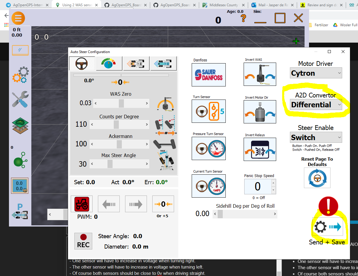
With this setup the ADS1115 will measure the difference between A0 and A1 (WAS_H and WAS_L).
For example
When turning right
left sensor - 5v - WAS_H
right sensor - 0v - WAS_L
WAS_H - WAS_L = 5 - 0 = 5v
When turning left
left sensor - 0v - WAS_H
right sensor - 5v - WAS_L
WAS_H - WAS_L = 0 - 5 = -5v
When driving straight
left sensor - 2.5v - WAS_H
right sensor - 2.5v - WAS_L
WAS_H - WAS_L = 2.5 - 2.5 = 0v
This part is very important:
- One sensor will have to increase in voltage when turning right.
- The other sensor will have to increase in voltage when turning left.
If you have sensors with 2 output (6 wire sensor) then this should be very easy to do.
If it is not possible to arrange the sensors like that mechanically, then I can help you make some simple code changes to make it work.
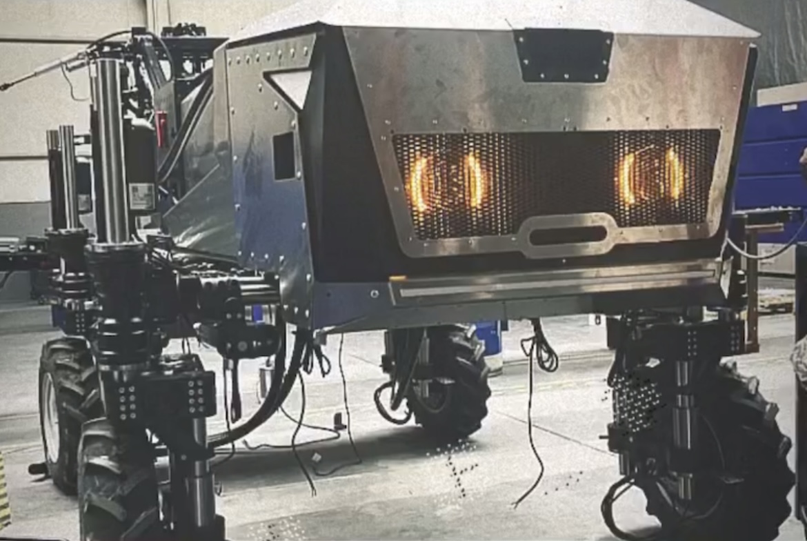
The robot looks very nice! Is this a personal project, work project, school project? Is there anyone online that I can follow the progress of the project?
2 Likes
Dear Buckhwheat;
Sorry for the late reply, I was busy with the project.
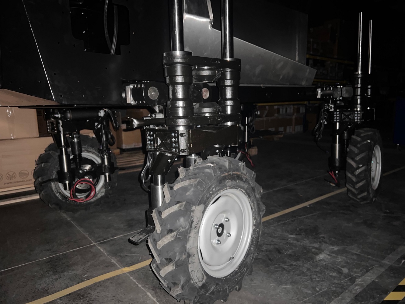
Thank you for your help, WAS worked in differential mode, this is a technology project, the sprayer robot has a working width of 12 meters and 48 nozzles, 120 l/min pump available, 4 wheel drive 5kW hub motors available, 4 lift actuators, 4 expansion actuators and 4 There are steering actuators, there is one that can do crab walking, but it is not mounted at the moment, it can rise around 50 cm, expand 40 cm, lidar and depth camera are available.


3 Likes