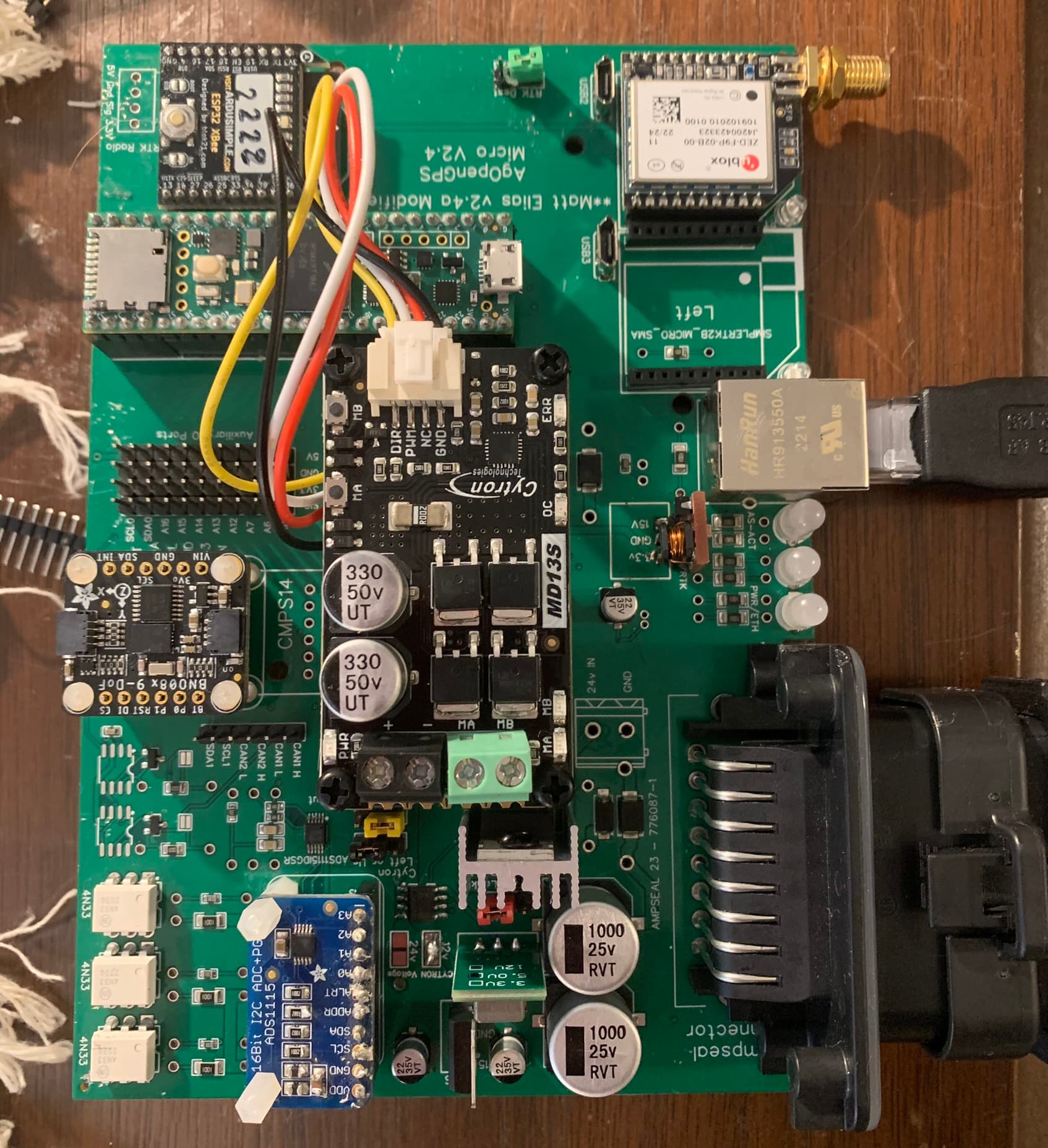
I have the micro version of the V 2.4 board. I bought this last year through the group buy. @m_elias put everything together and it looks awesome! I’m just now getting to soldering the parts that came with the board.
I am connected to my bench supppy (12V, 0.3A$ but I don’t get any lights. The WAS voltage converter is getting pretty hot and is reading 10V. The power pins on the xbee and F9P are not showing voltage. However the Teensy power pin is reading the proper 5V. I’m not sure where to go from there.
Could you show a picture of the board? How is the polarity of your voltage regulators?
I had to resize the image from my computer, it should now be in the original post.
I thought that the 3.3 was backwards, but it converts 15V to 3.3 right? So it looks backwards but according to the label I have it correct.
It’s been a while, did I completely assemble and test it? It looks like the WAS regulator is backwards but I think the other two are correct.
I know it has been a while, I had to re read the group message lol. I actually elected to solder the remaining parts myself, but then I got busy and am just now getting to it.
It would make the most sense given my test results. I thought I had it the same way as the picture, I’ll reverse it and see what happens.
Do you think this would also keep the board for energizing?
It look like you have two ads1115 are they both needed? Same question about IMU, although I don’t remember if there is an smd IMU at all on this version of the AIO
One thing - until electrical tests pass, unplug the Teensy, F9P, BNO and Cytron.
There’s a guide on testing the 4.1, that will give an idea what you can test on this board as things like the F9P, Teensy etc are powered with the same pins.
2 Likes
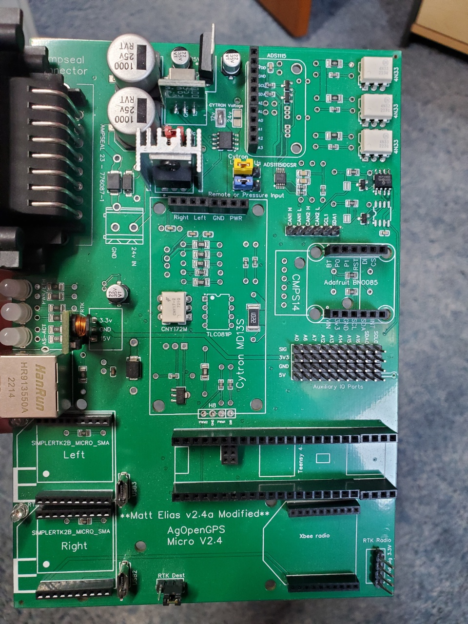
Here’s how the regulators should be. If you need another board let me know, I have this one left.
There’s no BNO on the pcb but there is an ADS so you don’t need the ADS module. @Damnbuffalo
I expect the WAS regulator is damaged. I would remove that regulator and all the modules as suggested by andy and then power up the board and check your 5V and 3.3V levels.
Thanks! I will remove all the peripherals as Andy suggested, including WAS as you said.
Should I order the same converter if this one is bad, or does it matter?
Some flavor of 7805 regulator
1 Like
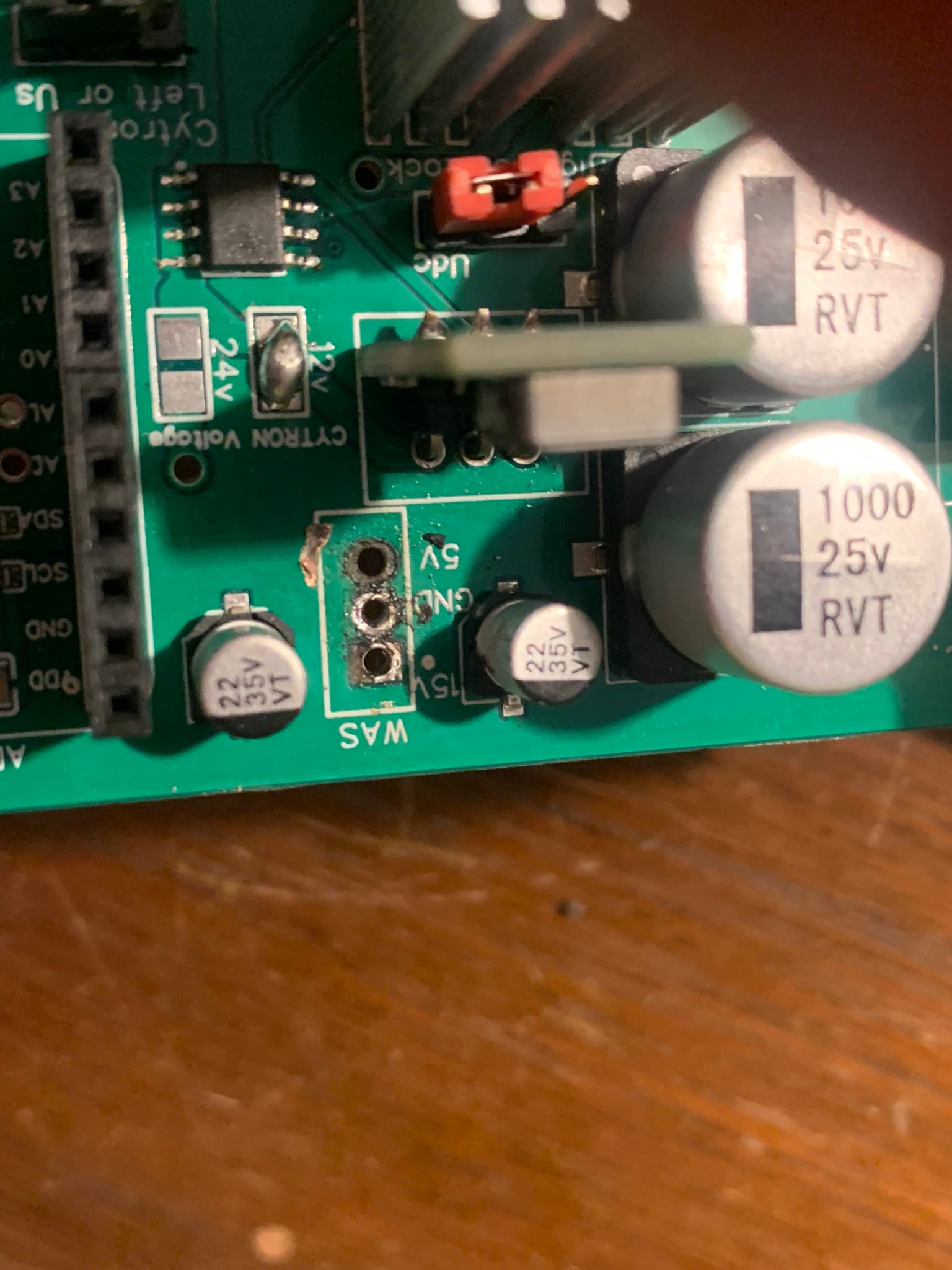
So… embarrassed to admit but in removing the WAS, I was to rough and inadvertently pulled out one of the through hole rivets. Do I need to repair my board or can I just fill the hole up with more solder?
As far as I can see, the 5v line is on the other side. So scratch a little af the green paint away and if neccessary also bend the 5v leg (after soldering the other two )on the new regulator. And resolder leg direct to line (Or prolong leg with wire to next 5v point)
Awesome, I will try bending the leg and tying into the trace.
Thanks!