V4 all-in-one PCB

here, this should work:
BackupProjects_AIO_v4_easydea.zip (1,0 Mo)

@nut Have you examples of setups requiring 2 canbus and motor controller? Or analog WAS?
As you Said v2.5 is an option for this case.

As discussed, for CAN only, Tony’s board is the one to use. It’s hided in the support folder under “Misc” :see_no_evil:

There was a lot of discussion while designing this board, the main point was to quickly release a board to correct some littles tings while keeping it almost compatible with the previous version and also to give the ability to upgrade to serial BNO and Teensy analog reading (without ADS1115) which is under testing this summer.

Not for motor controller, but for hydraulics, yes. I use a CAN valve in the steering setup so one CAN is always needed for the steering bus (this is normal left/right valve, not autosteer ready type), second CAN channel goes to tractor bus for reading armrest buttons, communicating with hydraulics etc. If there’s an existing WAS on the tractor, then that is hooked up to the analog WAS channel.

Good morning

I am a French farmer and I would like to install autoguiding on my NH G170 supersteer

Can I use this V4 all in one map for autoguiding?

Steering will be done by electric motor. Does this board support electric motor?

In addition I would like AOG to manage the rear linkage of the tractor

is the card compatible with what i want to do?

Thank you so much

2 Likes

We did all those things using the previous Standard board. So the micro should also be capable.

And here’s the code for Teensy:

Wiring was done in a way that we use the PIN that is directly wired to Teensy to trigger a relay board which in turn lifts the implement. That relay can override the switch that you use to lower / raise the implement. So you go to the field, lower the implement start driving then enable the “work switch” button on AgOpenGPS and at the end of the pass it does U-Turn and lift the implement.

(But if you ever decide to lift the implement middle of the field, etc. It could never lower it.)

At home you can simulate a shorter field and fine-tune the look ahead second so the implement is down by the time you reach the field. Farming simulator csak igazi traktorral :) AgOpenGPS szimulátor - YouTube

I’m located in Ile de France (but speak very little french) if you’re in that area I’d be happy to assist (and improve my french)

1 Like

jlcpcb is still missing some parts for this new pcb. Ampseals are easy to find elsewhere.
I found alternative header for teensy (JLCPCB Part #
C2883741) from Digikey, is it suitable?

But do you know any replacement for Onsemi MC7805CTG?

Hello Jhmach, Pat,

I placed the order with the first set 24_PIN.

JLBPCB sent a message asking if the orientation and placement of the components U3 U5 are correct or not and the following picture :

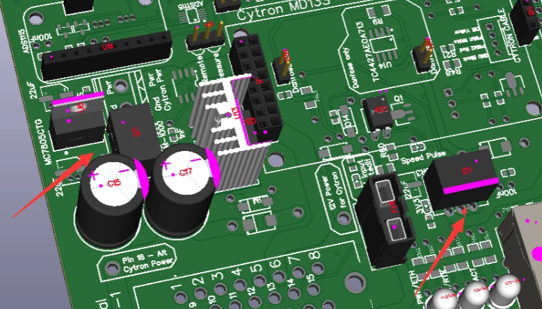
Is this correct in their picture ?

Thanks.

It seems correct imo
They could read the silk on the pcb! :roll_eyes:.
The default position is correct with the regs from the list.
Where the defaults from the BOM (Mornsun) available?

Yes, any 2.54mm, 8.5mm height, header will work. I typicaly buy 40 pins headers and cut to lenght

Most 5v linear reg would work, just check the pin order and orientation.
JLCPCB probably have many alternates but they are not in the list because the oriention was not verified.

I have these for an other project: AS7805AT-E1

Thanks Pat.
I used your default files and only U3 had to and could be swapped. No supply for U7/U10 and J2.

AIO V4.1 just arrived in UK, I’ve just finished assembling ready for testing this afternoon.

7 Likes

Hi is the standard version v4 already released?
Greetings hanz

No. It still lacks a little bit to be finished. Maybe later in the week or next.


What size are those ethernet holes in teensy. I have 2.54mm male heads. Between holes there is 2mm in teensy. I could cut my 2.54 heads but it seems that they are too big for CN2

1 Like

You need the smaller 2mm ones

2mm.

2mm are 0.5mm thick and 2.54 are 0.64mm. I will have to try find the right ones

They also have to be extra long to reach the female headers. The 2mm headers should just barely stick out past the 2.54mm headers. I think 13 or 15 mm overal length but I would have to check.

1 Like

If the lower socket is installed, then remove pin from strip and softly push true hole in teensy until they level with board. Then solder them.
I never use other pins. Works great for me.

So you use 2.54mm pins after you separated them from strip?

1 Like

That works as well the first board I did I forgot and did it that way but I think it is still a good idea to do it the right way.