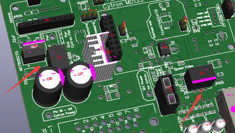
Here is the all new V4 all-in-one PCB.
This file will be the Micro version only. the Standard is on the way.
The changes to be noted:
Status LEDs
work, steer, and remote circuit
speed pulse circuit
Danfoss circuit
alternate Cytron power in pin and Grove connector
reverse polarity detection
heavy motor traces
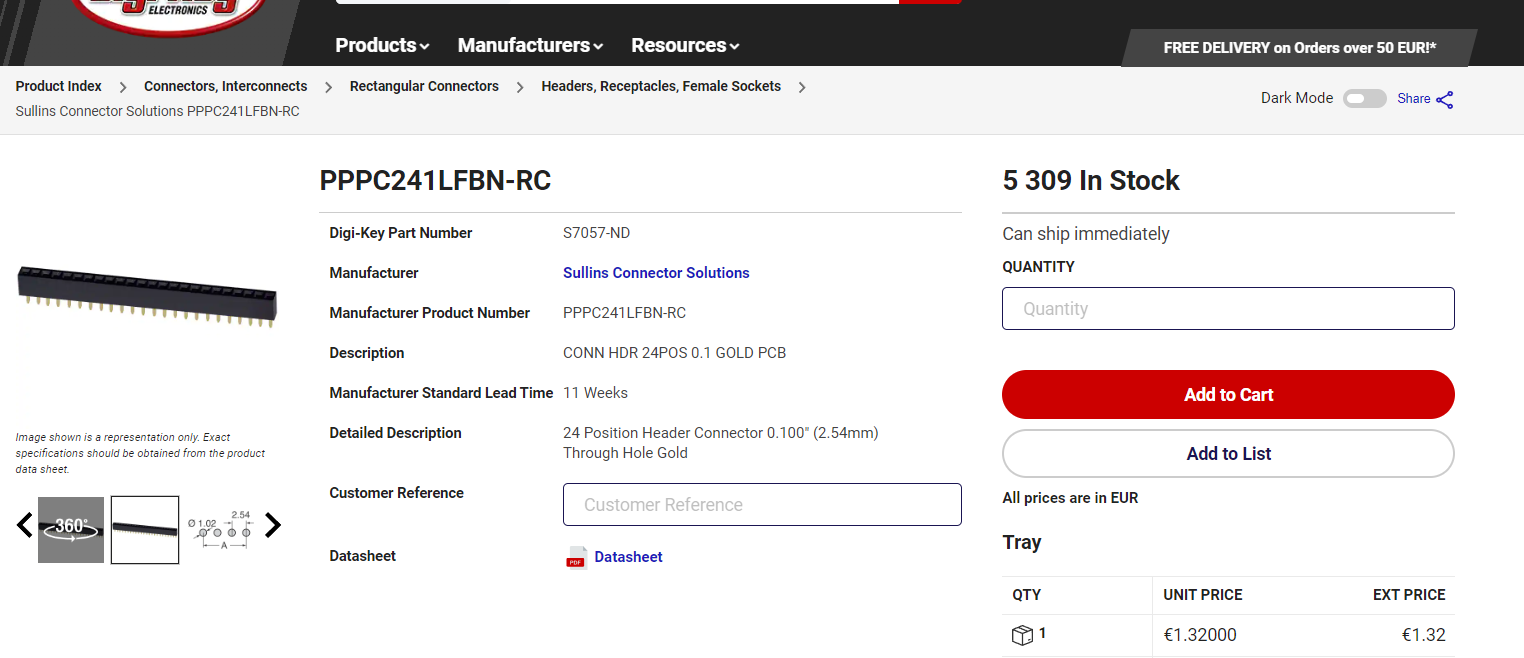
new available parts BOM
much better protection at inputs
and
expandable for future improvements
Status LEDs
there are 3 power LEDs for 5v, 3.3v, and 5v WAS. Just connect power to the board and see if the LEDs are lit. Then check voltages to make sure they are correct. Headers with the voltages labelled have been added for this. (Then add the Teensy, F9Ps, and IMU)
work, steer, and remote circuit
All 3 circuits have polarity protection, better resistor values, and LED status. Also there is an onboard button to access the feature for testing.
speed pulse circuit
speed pulse now uses the same optocoupler as the work, steer, and remote circuits. It also has polarity protection and better circuitry putting much less load on the Teensy.
Danfoss circuit
The Danfoss circuit is all new with better suited components to operate the valve. The old design had a lag in function to the left direction and required a code modification to make it work properly. The new circuit needs no help from the code. It is equal in left and right directions.
alternate Cytron power in pin and Grove connector
pin 18 is now available for anyone who wants separate power input for the Cytron. 24v inputs and so on. Also there is a pad to solder and optional Grove connector although we suggest to cut the cable and solder the lead.
reverse polarity detection
along with bigger diodes and an onboard fuse, this board had a LED that will light up if the polarity is reversed.
heavy motor traces
The motor traces have been increased to the absolute maximum possible without changing the pinout of the AMP connector. There is only one wire to solder on the board, compared to three wires on V3.
new available parts BOM
all of the parts in the previous versions that were constantly “out of stock” have been updated to better stocked parts. Though there will always be shortages, there should be less issues with V4.
much better protection at inputs
Aas mentioned above, all inputs have diodes added at the input to protect from damage caused by wires being pinned incorrectly. There are still some things that need special care when connecting, such as WAS, and CAN bus.
expandable for future improvements
No one wants to put a board in that is soon to be obsolete, so this board has the future improvements that are being discussed onboard.
RVC-BN08x is already wired on the board. It will likely be the next great improvement for the single GPS users. RVC cannot work at the speed it’s capable of with the ADS1115 however. i2c has to be removed from the Teensy to enable the RVC mode to run at it’s intended speed. A hat that looks like the ADS115 has been developed to use the Teensy Analog/Digital converter and obsoleted the need for the onboard ADS1115.
The code for these improvements are still in the future, but when they come, the V4 board is ready for them.
The whole team has worked tirelessly this winter to have this board ready for spring seeding. That is the reason we have kept the pinouts on the AMP connector mostly the same. We removed 1 CAN bus(pins 18,19) and added a pin for direct Cyrton power(pin 18) The rest of the pins remain the same.
The Cytron can still be powered from the 12v in pin as it has always been as well.
Here is the new github link for harware
https://github.com/AgHardware/Boards/tree/main/Boards/TeensyModules
The new V4.5 board is on a new thread here
Order the AIO v4 micro at JLCPCB
This is a short video to show how to order the AIO v4 for AgOpenGPS