hey guys!
i got the v4.2 aio board. i managed to get all the things (WAS, antenna) connected and working.
the only thing that doesnt work is the motor. i tried it in the extended steering settings and i tried it while driving next do a A-B-line and activiting autosteer. no reaction from the motor.
i cannot test with the MA and MB button anymore because i have done the freewheel mod.
here is a pic of my pcb powered with a 12v power supply (test setup).
i want to use the motor with 24 volts later. for demonstration purpose i have also hooked up pin18 (cytron in) to the 12v power supply:
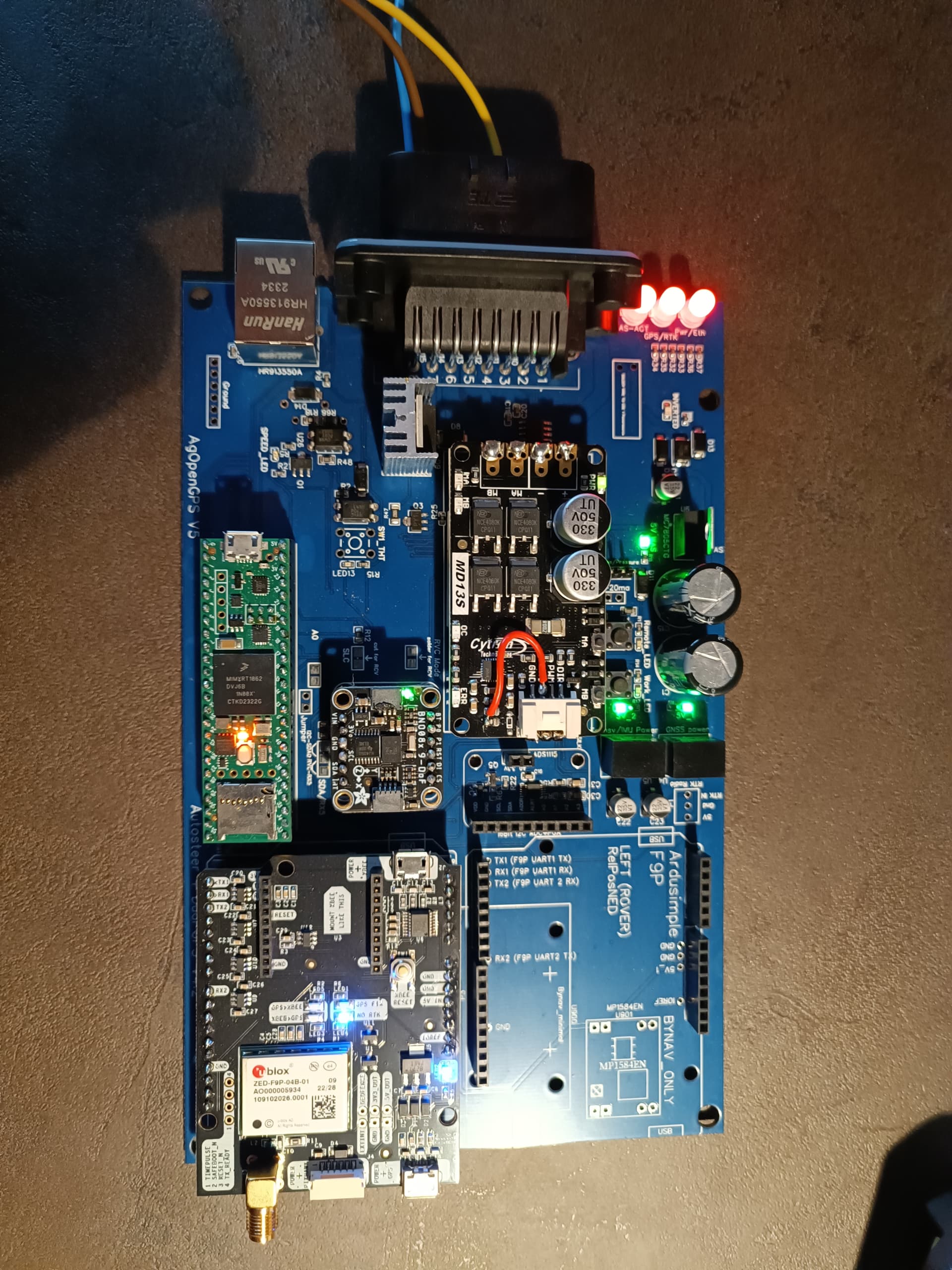
after powering up the pcb i measured voltage on the cytron input and got 12v as a result. so power from pin18 seems to get to the cytron. when testing pwm output in AOG i could not measure any voltage on MA and MB right next to the power input on the cytron.
freewheel mod:
i hope i did the freewheel mod correct as i found 2 or 3 different ways where the wire has to be soldered.
I have to drop a link to the other pics, because i can only upload 1 as a new user.
https://drive.google.com/drive/folders/11hUWBiofz7AQrC64SvzwWrZSS3NGDVUU?usp=sharing
i also was looking at the 3 soldered pins next to the white socket for the cytron cable. i did a “beep” test with the multimeter and could get electrical continuity between the 3 header-pins and DIR, PWM, and GND.
so there shouldn’t be a problem with the soldering.
also not sure if the pins on other end of the cytron where +,-,MA,MB are located are soldered into the right position. my pins go into the left of the two columns on the board (red circle).
pink circle: do i still have to cut the traces? i think i read that with version 4.2 this issue should have been corrected.
i did not use any external relais for the freewheel mod. could this be the problem?
do i have to set a jumper(wire) somewhere on the board?
regarding the green circle:
i recieved the pcb from jlcpcb without the steer switch.
i am going to mount an external switch later in the cab. will the missing button on the pcb cause any issues?
should i get one and solder it in?
thanks in advance
Georg