V4 all-in-one PCB

I wonder if someone can point me where the support files zip now is ? Have searched high and low ! Thanks

For the hardware?

Yes - thank you. I think it used to be with each of the program version downloads. Need to change my machine control to udp

1 Like

hey guys!

i got the v4.2 aio board. i managed to get all the things (WAS, antenna) connected and working.
the only thing that doesnt work is the motor. i tried it in the extended steering settings and i tried it while driving next do a A-B-line and activiting autosteer. no reaction from the motor.
i cannot test with the MA and MB button anymore because i have done the freewheel mod.

here is a pic of my pcb powered with a 12v power supply (test setup).
i want to use the motor with 24 volts later. for demonstration purpose i have also hooked up pin18 (cytron in) to the 12v power supply:

after powering up the pcb i measured voltage on the cytron input and got 12v as a result. so power from pin18 seems to get to the cytron. when testing pwm output in AOG i could not measure any voltage on MA and MB right next to the power input on the cytron.

freewheel mod:
i hope i did the freewheel mod correct as i found 2 or 3 different ways where the wire has to be soldered.

I have to drop a link to the other pics, because i can only upload 1 as a new user.
https://drive.google.com/drive/folders/11hUWBiofz7AQrC64SvzwWrZSS3NGDVUU?usp=sharing

i also was looking at the 3 soldered pins next to the white socket for the cytron cable. i did a “beep” test with the multimeter and could get electrical continuity between the 3 header-pins and DIR, PWM, and GND.
so there shouldn’t be a problem with the soldering.

also not sure if the pins on other end of the cytron where +,-,MA,MB are located are soldered into the right position. my pins go into the left of the two columns on the board (red circle).

pink circle: do i still have to cut the traces? i think i read that with version 4.2 this issue should have been corrected.

i did not use any external relais for the freewheel mod. could this be the problem?

do i have to set a jumper(wire) somewhere on the board?

regarding the green circle:
i recieved the pcb from jlcpcb without the steer switch.
i am going to mount an external switch later in the cab. will the missing button on the pcb cause any issues?
should i get one and solder it in?

thanks in advance
Georg

Hi
With just a quick look at your first picture I would say the missing PWM2 lead from pcb to the cytron is your problem

This signal is not provided by the 3 pins header. Typically you use the connector provided with the cytron and solder the red wire (or all) to the board.

Also in AGO if you open and expend the steer set window you can see if the board is trying to send power to the motor (PWM value)

4.2 AiO doesn’t have issues needing correction.

Regarding the steer button my boards came from jlcpcb without it as well. You dont need it. The external switch works fine without it.

No you dont need external relays with the cytron modification.

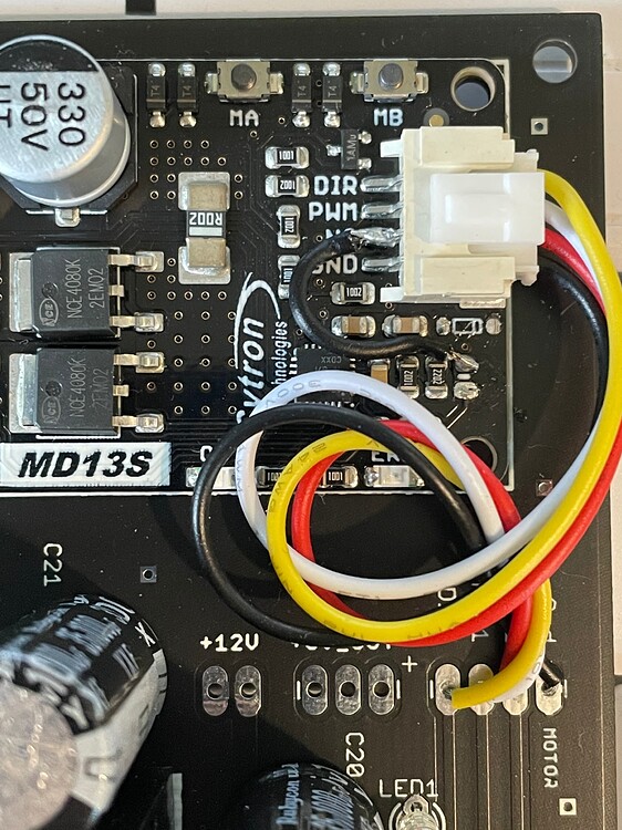
You soldered the wire on the cytron to a different place than mine but like you said there are several places that will work. i dont know if that is one of them.

(Edit) Did some poking around and I couldnt find an example of someone soldering the wire to the pad you did. Yours is on the outer pad and theirs is on the inner. I think that might be your problem. Take a look at this post:

m_elias

Sep '21

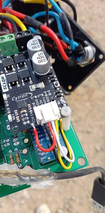
This picture from @buched is an example of an error, he said “I hope you do not wire same”.

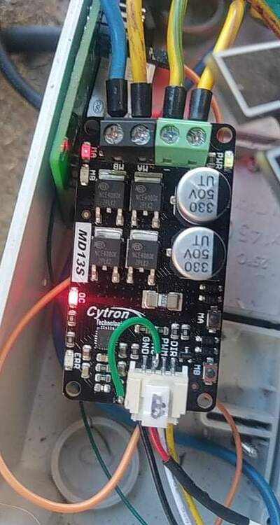
The difference between @PotatoFarmer’s picture & @buched’s earlier picture could just be a different place for the same trace. Both report it as working. I used @PotatoFarmer’s example myself.

@PotatoFarmer

@buched

2 Likes

thanks i will try that later. just one more question… do i have to unsolder the 3 pins next to the white socket?

Hello,
i have 2 problems with my standard aio V5 pcb board (I know this is V4 forum, but i don´t know where else to ask).

The first problem is with agio not showing IMU connected, but when i look at the numbers on tilt, it normally shows them and they are changing as I am tilting the board. The ON LED shines green when powered up.

The second problem is with motor (24V phidgets). Everything except motor works normally (WAS, antena). I tried extended steering settings, with A-B line and activating autosteer (it lights up green but after while it disconnects), tried steer wizard, MA and MB buttons on cytron just light up when pressed and motor doesn´t turn (i haven´t done the free wheel mod). I tried powering the motor with 24V and it turned, so the motor is not the problem. When I measured power with multimeter, to the cytron (+,-) goes 24V, but from pins on ampseal to the motor there is no voltage when autosteer is turned on. Only thing that comes to mind is the PWM2 hole for cytron is not connected to anything and i don´t know if it should be connected.

there is a link for other pictures, bcs I can only upload one
https://drive.google.com/drive/folders/1G71hKTX_hAVXn5D-lWUWxblbds3VLkFo?usp=sharing

Thanks in advance for any ideas

don’t see that you have the jumpers on to use the motor or valve, maybe that’s it?

is there a jumper that has to be set with the 4.2 boards too?

You’re using an early v2.4 it has a missing trace for the pwm2 needed to operate the lock circuit.

Yes you’re right, I didn’t read the post correctly, just spotted the version of PCB and the usual problem.

For testing fit the jumpers it will work.

are you talking about the jumper that states: Remote/Pressure?
i am using a phidgets motor. so do i have to set the jumper to remote or to pressure?

Sorry ignore what I said there I missed the part about V4.2 board. The V4.x have no jumpers for motor

1 Like

No you can keep them and solder all 4 wires from the cytron cable if you want.

@schoerdinga in your case make sure you have installed the red cable.
Then double check your cytron modification as someone said you could have soldered your wire on the wrong pad, I can’t confirm this.

i soldered the 4 wires to the pcb and plugged them into the cytron.
next i resoldered the “freewheel-wire” to the same pad as in potato farmers picture in post 448.
motor still not working.

will the motor turn if i use the left/right buttons in the steer wizard or wont this work like the MA/MB buttons since the freewheel mod?
i also tried driving next to the A-B-Line, activated autosteer, no reaction from motor.

now i ordered a second cytron to test the cytron before doing the freewheel mod.

would it be possible that i damaged something on the cytron by using the wrong solder pad for the freewheel mod?

thanks

remote is to use a physical button to disconnect the autosteer and pressure is to connect a pressure regulator that cuts off the autosteer when you turn the steering wheel (normally fitted to the hydraulic valves for autosteer)

1 Like

Ignore the burnt bits(theres a story behind them!) but you’ll need some jumpers on these pins
If youve doctored the cytron for the freewheel mod the ma mb buttons will no longer work. The easiest is to just use the relay for the freewheel mod

Those diodes have life experience now :rofl:

:rofl::rofl:its all part of the journey. I can laugh about it now but i couldn’t at the time. I used a wrong steer switch i think and it back fed some current. Luckily no major components were damaged and i just swapped it all to another board