Some background: I have been experimenting with GNSS-devices (mostly u-blox ZED-F9P) for some time and also stumbled upon AgOpenGPS at some point. Thought back then that it would be interesting to try this, but just didn’t have enough energy/time. But recently bureaucrats (not sure if local (Finnish) or EU) decided to kind of incentivize (that is, force you to choose from some options, one being related to precision agriculture, that is fullfilled by automatic steering) installing automatic steering to a tractor so I decided to finally give it a try.
Although I had a NTRIP-base already working and also had some kind of understanding of ZED-F9P, otherwise I pretty much started from scratch. After spending some time reading posts on this forum and elsewhere, watching videos and such I decided to order the new AIO Micro V4.1 board and build the system around it. With the help of the documentation and videos it was a breeze to order the PCB and other stuff, programming teensy and the like. Big thanks to people here sharing their work for everyone to use!
Video:
")
A more detailed story:
Otherwise there was not much to adapt, but wheel angle sensor and turning of the steering wheel needed some pondering.
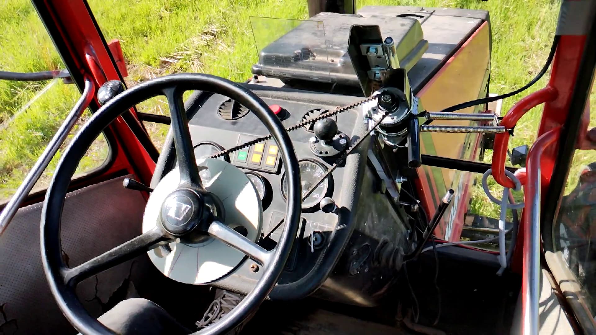
For steering wheel I ended up using a “half-toothed” belt drive. There wasn’t much space under the steering wheel (probably the motor could just fit there if using 3D-printed gears attached to the spokes). Belt-drive allowed to throw the motor away from below the steering wheel. I also tend to take a grab on the spokes occasionally (bad habit?) so attaching something to them would make it difficult.
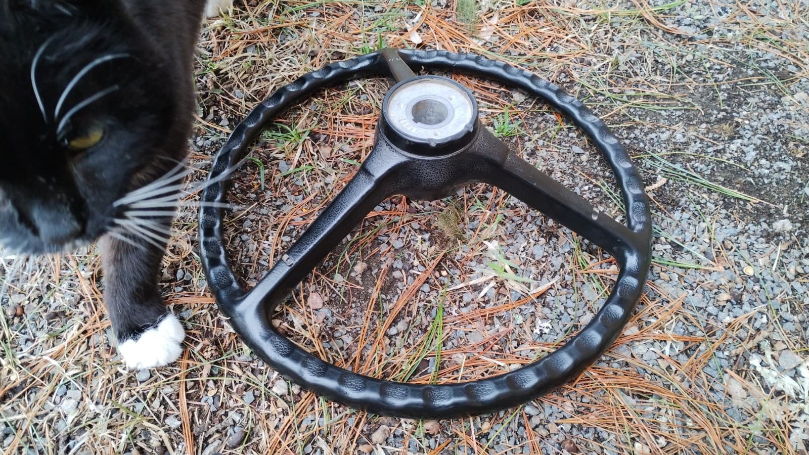
Steering wheel before modifications:
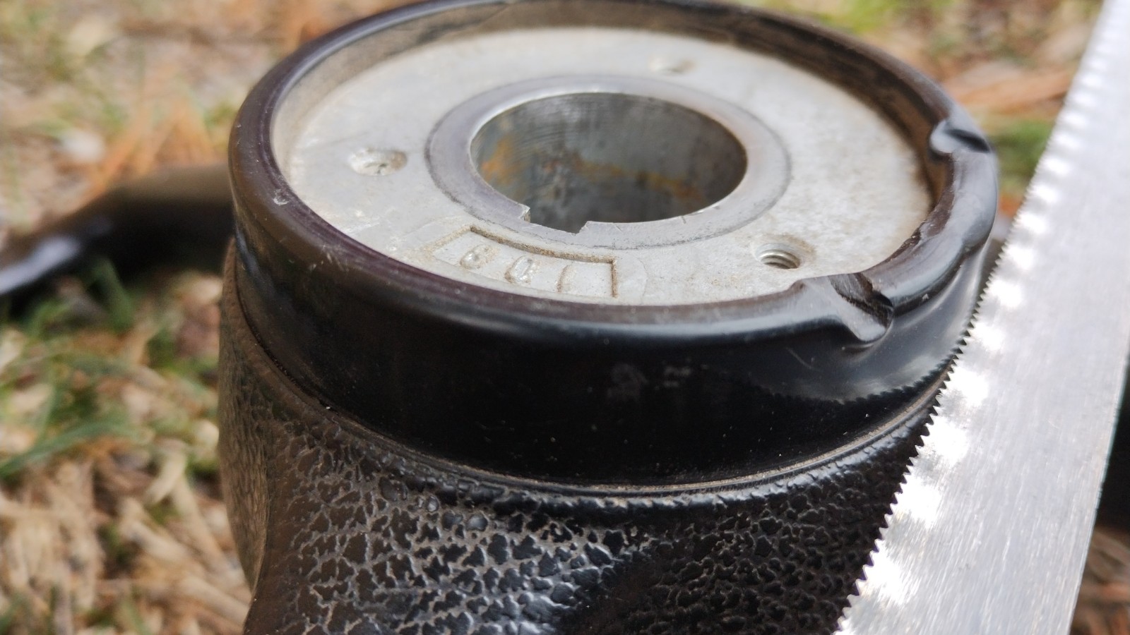
There were 3 threaded holes on the hub. They were only something like 3.5 mm so I later drilled them bigger (not yet on this pic) and made M8 threads to them so that the pulley could be attached more sturdily to the hub. To make centering easier i also cut part of the plastic rim away (saw blade on the picture where it was cut):
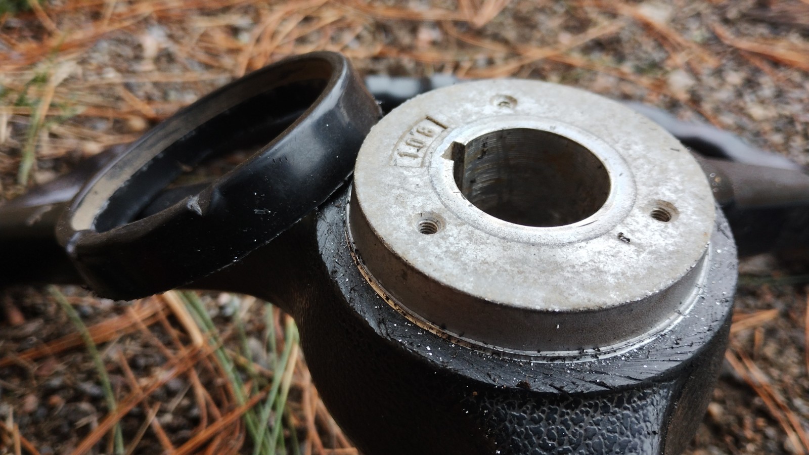
Plastic rim removed (it almost fell off by itself after sawing):
Here is the steering wheel side pulley and belt:
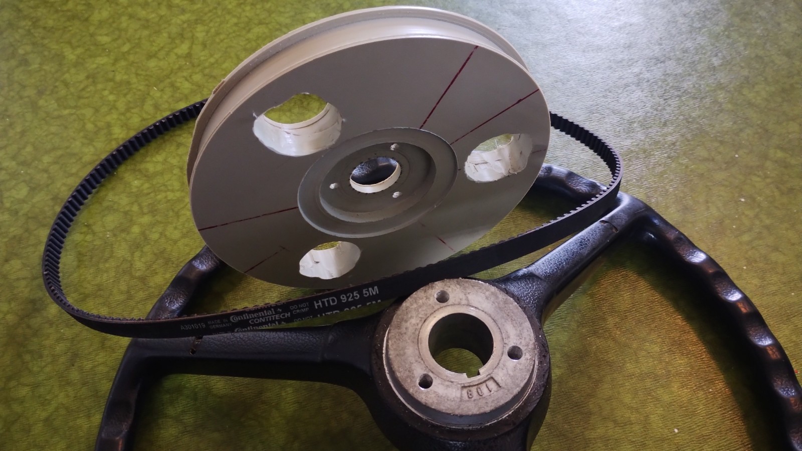
Pulley is made of polypropylene plastic plate, 20mm thick, using a lathe, final diameter being about 17 cm. The three bigger holes were drilled (and then expanded more, since the initial holes were too small. ![]() ) to it to make it easier to attach it to the jaws of the lathe. They also allowed keeping the piece attached to the lathe all the time while machining the parts that should be concentric.
) to it to make it easier to attach it to the jaws of the lathe. They also allowed keeping the piece attached to the lathe all the time while machining the parts that should be concentric.
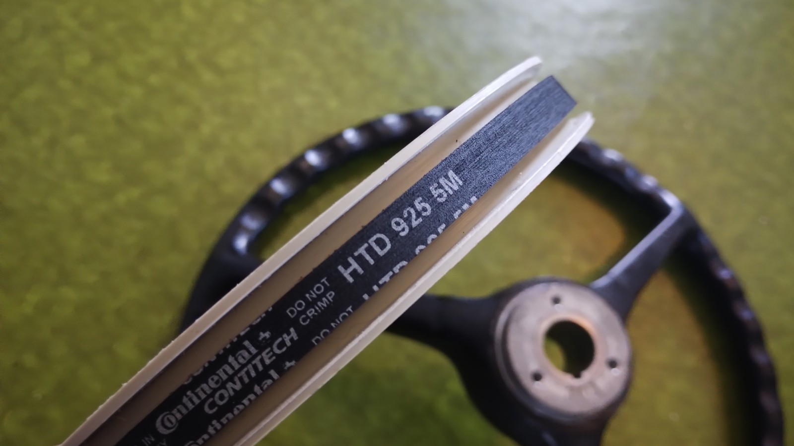
Although the belt is toothed, this pulley isn’t. This allows slipping if turning the steering wheel by hand when automatic steering is engaged. On the other hand slipping makes using the current-based disengagement difficult. Tried it a bit, but didn’t get it working. Using right tension and limits it probably could be made to work, though. Original idea was to make the bottom of the groove a bit convex to make the belt self-centering (when not slipping), but now it’s straight instead. Probably better when the belt is slipping to avoid driving the belt to the side.
Complete steering wheel assembly with motor (12 V, RS components 420-625), door hinge, pair of springs, 14-teeth pulley and stuff:
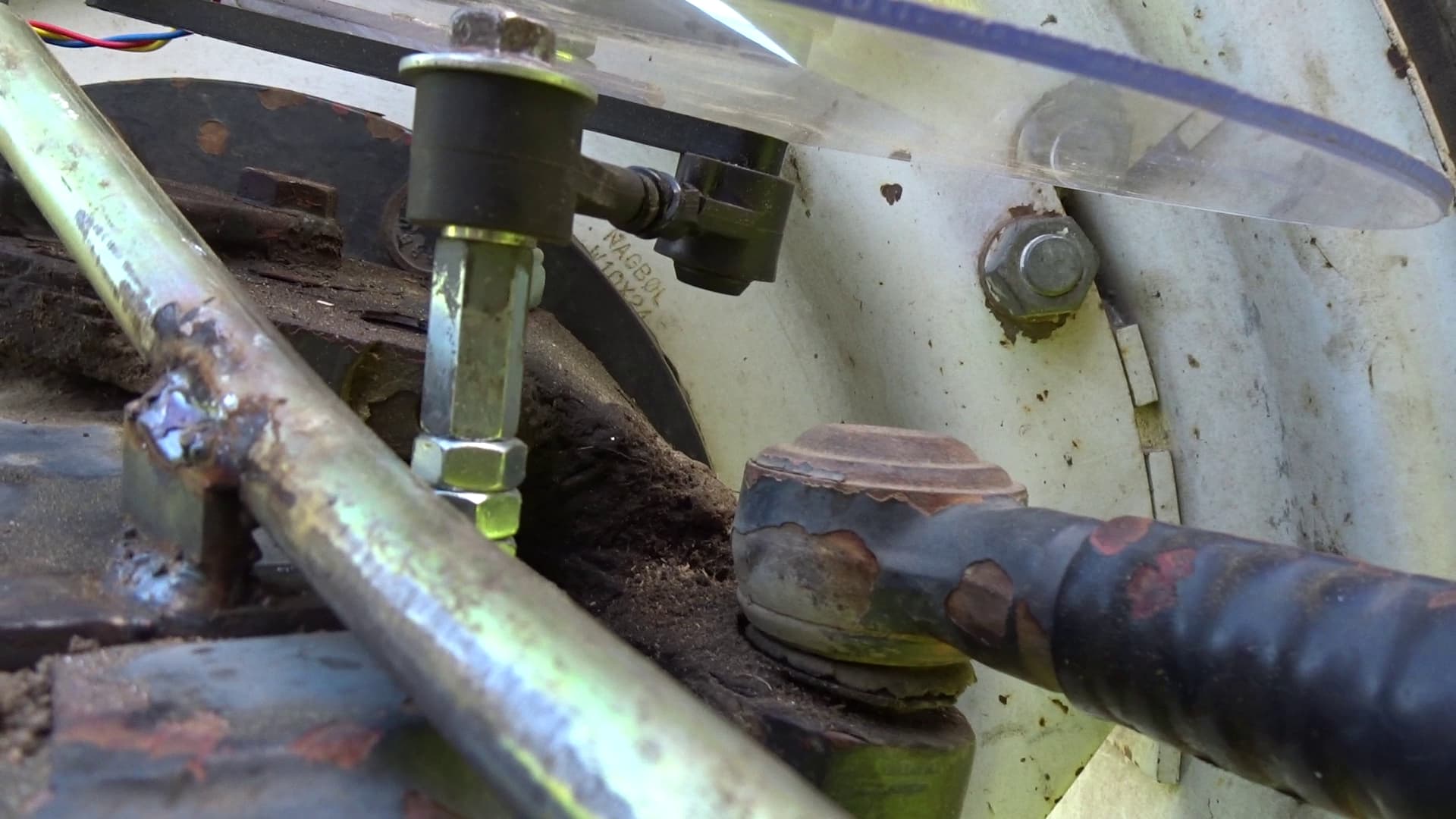
For WAS I used the same Land Rover suspension height sensor (RQH100030) that many here have used already. I ended installing it to 2mm polycarbonate sheet that is installed above the right king pin (so that the sensor rotates with the wheel):
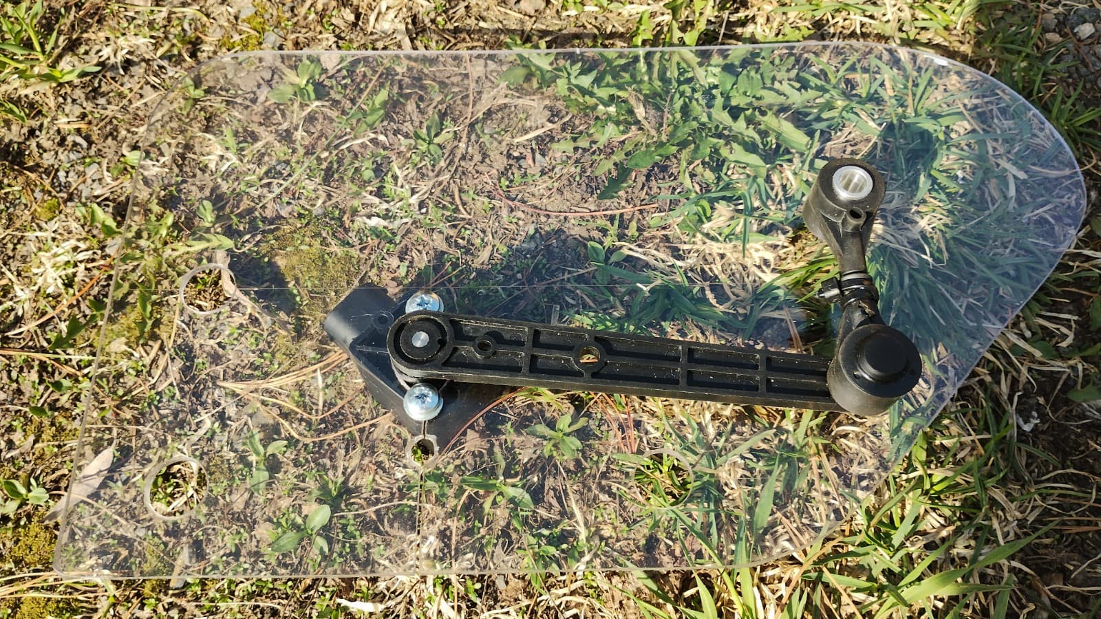
Although it’s hard to see in the picture the sensor is installed into a drop-shaped hole and there is a cut to the edge of the sheet. Polycarbonate is somewhat flexible so it allowed the sensor to be slid into place (needed some force, though, to be honest).
Here’s the final assembly:
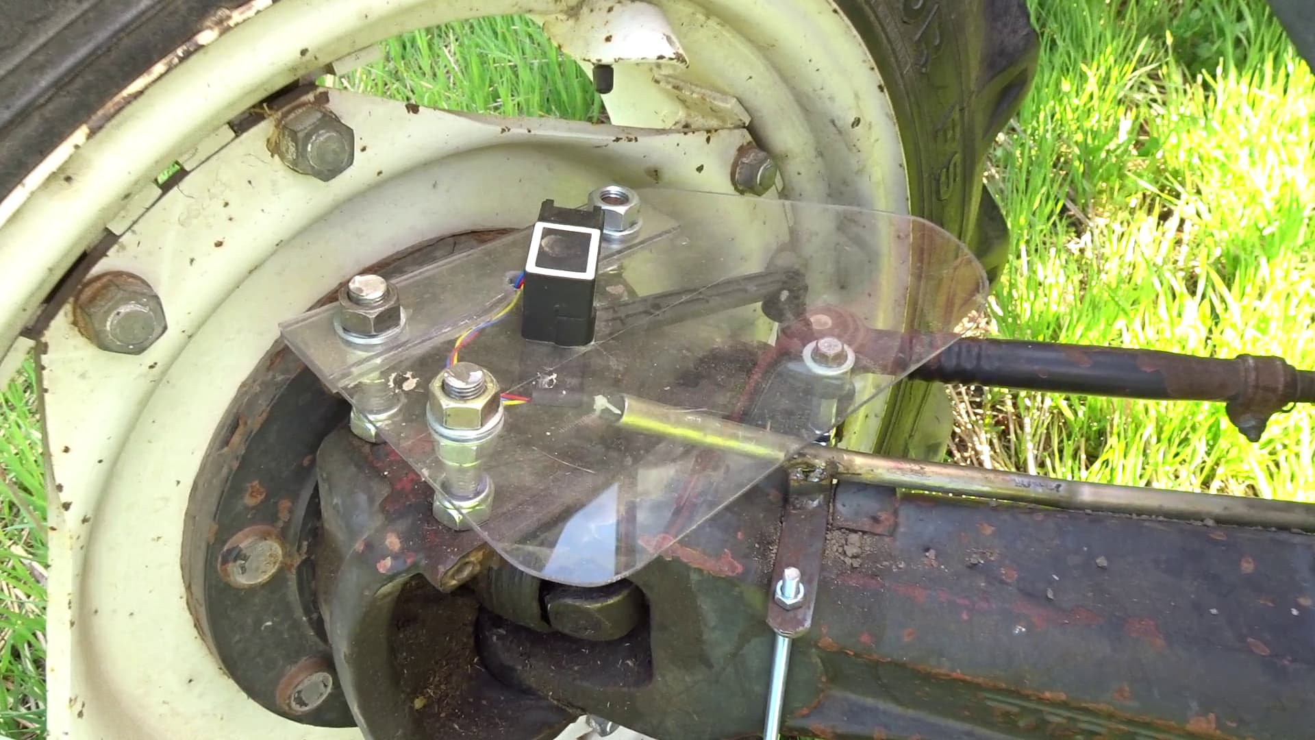
There were 4 (although only 3 used to allow the sensor’s arm to move all the way) M16 threaded holes to attach the polycarbonate sheet to, so at least that part should be sturdy enough. The sheet itself is quite flexible, but on the other hand polycarbonate can withstand quite a lot of bending before breaking.
Second, shortened arm of the sensor is attached to a stationary point on the front axle:
Electronics (All in One, Ver 4.1 Micro) are in a plastic box with a transparent lid:
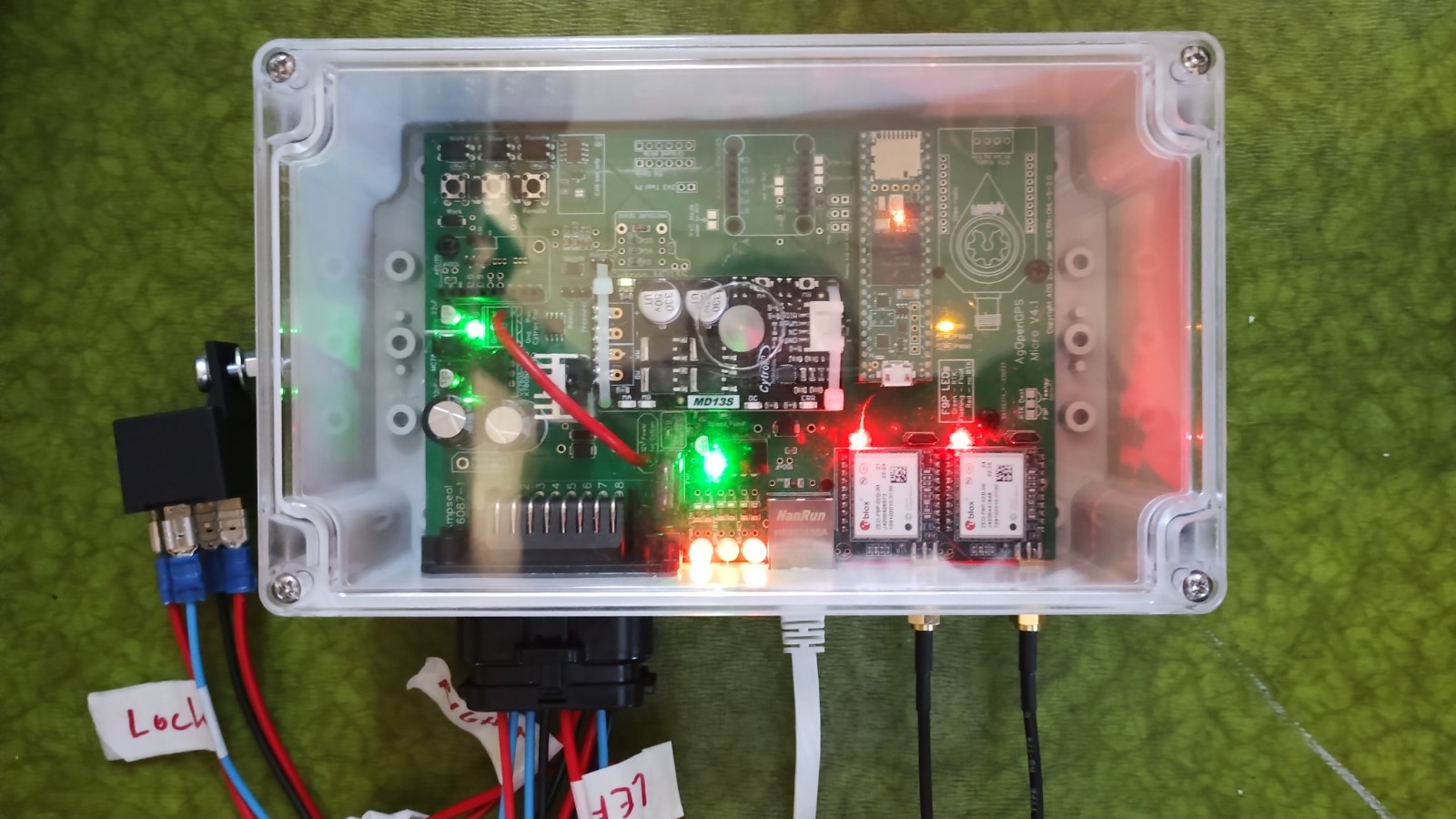
This is just thrown into the “roof box” of the tractor (where radio previously was).
Some lessons learned:
- Install the WAS so that it works on the whole range. This installation goes over the range when steering right, probably partly due to ackermann. WAS can be installed to any angle in this when drilling the holes after finding the right angle.
- Avoid shortening the secondary arm of the WAS. I almost broke it beyond repair while trying. “It is just this metal shaft in a rubberish material. How hard could it be to remove and re-insert”. Well, it was hard.
- Use a bit larger (“wider”) box (if not using 3D-printed one). It was difficult to insert the PCB with the big connector into the box (had to make the hole bigger than the connector to make it even possible). Ardusimple boards also had to be inserted after the board was already in place, which caused some fear of bending the pins.
- Cut the holes into the steering wheel side pulley so that you can machine the whole thing (using a lathe) without fearing hitting the jaws with the cutting bits.
All in all this whole project was surprisingly hassle-free, thanks to all the information provided by people here and elsewhere. So thanks to all contributors (SW, HW, manuals, videos etc.) again!