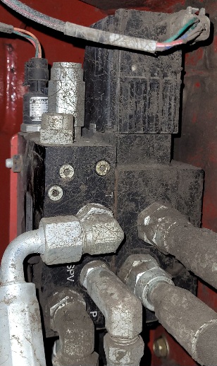
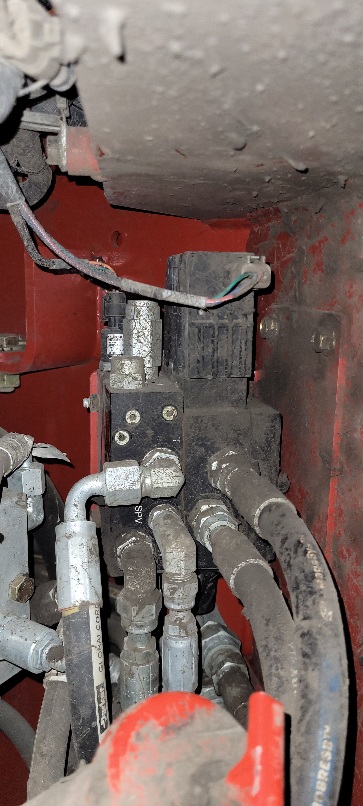
This valve is currently part of a Trimble auto pilot system. Looks like a three wire connection on the valve control with another three wire for the pressure transducer? Is this a danfoss? Anyone have experience connecting to this? It’s on a versatile Delta track.
Yes this is a “Danfoss” valve in the AgOpenGPS world. Lots of people use it, just follow the wiki steering with Danfoss instructions.
Ok thank you!
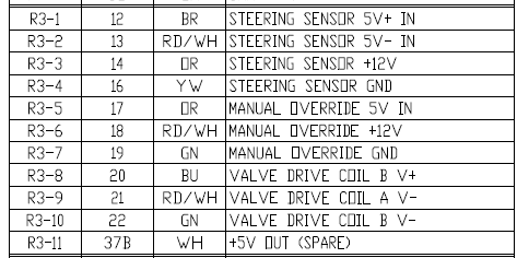
Ok so I want to make a cable that goes from the 23pin AMP on AOG to a 12Pin Deutsch plug that my valve, pressure sensor, and WAS are currently wired into. Each component is 3 wire so I guess only 9 pins are actually being used. I’ve attached the pinout for this plug.
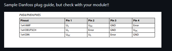
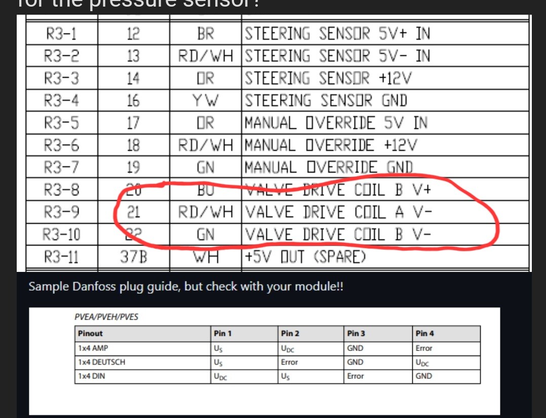
I don’t quite understand the wiring instructions for the valve. What do Us and Udc stand for? There is Valve drive coil B V+, A V-, and A V+.
Also wondering about the steer sensor. I verified that it is only a three wire sensor and the pinout shows four Steering Sensor pins so I’m assuming the +12V one isn’t being used.
And the AOG pinout only shows two connections for the pressure sensor?
Looking at the wires going to the valve GN,BU,RD/WH those would match the pinout for B V+, B V- and A V-. Im not saying the wires might have changed colors somewhere ![]()
WAS
Yellow - GND
Brown - Signal
White - 5v
Pressure
Green - GND
Orange - Sig
Red/White - 5v
Valve
Blue - Valve power
Red/White - Signal
Green - GND
Ok so like this? Obviously connect the GND’s to ground. Take 5V for both WAS and Pressure from Pin 1? Valve from 6 and 7?
WAS
Yellow - GND
Brown - Signal - AMP Pin 2
White - 5v - pin 1
Pressure
Green - GND
Orange - Sig - Pin 10
Red/White - 5v - Pin 1
Valve
Blue - Valve power - Pin 5
Red/White - Signal - Pin 6
Green - GND