I don’t have any documentation (I should ![]() ). Just have to use it to see how it works. It isn’t set up for turn compensation. Each product is only set up for one rate. It might be possible to treat products as sections. Ex:, have product 1 for the left section with a separate flow meter and adjust valve, product 2 (the same product just a different section) for another section and so on. Then do the math on the estimated speed of each section taking into account turning and distance from the centre of the machine.
). Just have to use it to see how it works. It isn’t set up for turn compensation. Each product is only set up for one rate. It might be possible to treat products as sections. Ex:, have product 1 for the left section with a separate flow meter and adjust valve, product 2 (the same product just a different section) for another section and so on. Then do the math on the estimated speed of each section taking into account turning and distance from the centre of the machine.
1 Like
I see, I might get one of the programmers that works with me to have a look at the left and right speed of the booms and see if we can break that part out into something usable. Thanks for the advise!! Even just having one flow meter is a huge step for us on our farm.
Hi Sparky; Thanks to SK21, I learned a lot and I was successful in ratio control, sprayers101 is a useful site to learn, in my personal opinion, the most efficient system in return compensation is the PWM nozzle system, there is even a topic about it. I was getting the best accuracy results of flowmeter from ARAG brand, but for the system I will install for a friend of mine, ARAG said the product delivery is 32 weeks, so I bought 1 piece from Polmac to try it out.
https://discourse.agoopengps.com/t/diy-pwm-nozzle-and-rate-control/8034/49
1 Like
Inside AOG, left and right tool speed is calculated already. May be possible to use this.
1 Like
Wow Thankyou both for the info!! I do vaguely remember watching one of Brian’s videos and I think it covered left and right tool speed and how he worked it out, maybe that’s where I thought I saw the turn compensation… I’ll have a look at the link you shared @whiterose!! I’ll try upload some pics of what I’ve built, I’ve approached it from an industrial electrical point of view as that’s my trade, and I hope what I’ve built can handle the bouncing that will happen on the trailer.
Everyone here and I are people who are ready to help in any way, please ask anything on the topics that I know. While adjusting the flow rate according to the speed, the most important factor is the PID values. By changing the gain setting according to the type of your engine, the engine rotates in the fastest way and tries to adjust the desired flow rate by turning the valve.
1 Like
@whiterose my plan for commissioning the system first off was to run AOG in simulation mode and run the sections and flow control as if I where really driving it, that way I could run the machine at different speeds and measure the volume that comes out of the nozzles. I guess the next question is what to do if the calibration is out? We’re exactly are the 3 main values for the P,I &D? And which ones can I change? Assuming speed is one of them and it’s not a variable I can tune… I see there is a cal function, does that take care of the rest? I understand the basic principal of a PID loop but I am no programming guru. I do work with a few though so I have people I can call. Do you have any info on the arag gear you used? I’d put money on it that we are running similar gear and your set points might be a real good place for me to start!!
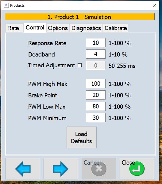
In the app here is the Control settings page. The P value is Response Rate. I and D are not used. High Max is the maximum adjustment value above the Brake Point. Low Max is the maximum adjustment value below the Brake Point. Timed Adjustment can be used to adjust flow for a set # of ms and then adjustment is paused for 3 X the set time before adjustment is made again. It helps to smooth out the flow.
2 Likes
Weder, SK21, Brian, Torriem and MTZ are very good at ratio control, I learned everything from them, and I would like to share the 2019 articles with you, especially Brian’s video.
I’m using weder’s ino code, if you want I can send it to you, and I can share the edits (PID) I made in the code with you.

2 Likes
@SK21 G’Day again!! I’ve built out my new arag section and rate control and I’m at the point of commissioning, I’ve driven the section valves open and closed by bridging the 12 volts to the signal, along with the proportional valve by pressing the manual buttons on the cytron to drive it open and closed. I also have a light up on the flow meter. So all good on that front. When I connected up the arduino with the RC 5 code onboard and ran AOG in simulation mode I couldn’t get the sections to switch on… I’m looking at the MCP addressing, I’ve left all the pins on the addressing off, so no doubt that’s an issue, and also I’ve had a look in the code and found a few lines that I may need to uncomment out relating to the MCP relay pin out. Can you help me out with how I’m to handle the MCP? I’m intending on using the relays built onto the RC 5 board and not an external relay board…
Which ino sketch are you using? Is it RCnano? The address pins should connect the 0 and centre pin of each set. This gives the default address of 0x20. In the user settings of the sketch “UseMCP23017” should be 1. The relays are already defined starting on line 60.
1 Like
I’m using RCarduino… should I be using a different sketch?
RCnano is the latest version and the best one to use. It is here Release fix remote switches · SK21/AOG_RC · GitHub in the file RC.2.1.16.
2 Likes
Thankyou!!
Your welcome.
Still no luck with those address pins bridged, I’m trying to connect via USB serial, so I’ve selected that in the code, do I connect via ag io or do I leave ag io machine port not connected and connect through the comm setting in ag rate? I get a yellow shaded icon in ag rate where it says MOD and AOG is green. I’m assuming MOD should go green? Also, does having it in simulation mode affect it connecting the my arduino?
The nano should be connected to the rate app through the comm setting. Yes the icon should turn green. If it is yellow then it is in sim mode. The sim mode for the product you are connecting to the nano should be unchecked. You can still do the sim mode on the other products. Each product has a unique module ID and sensor ID. If the first product is module 0 and sensor 0 the second product could be for example module 0 and sensor 1 or module 1 and sensor 1. The module ID for each nano is set in the sketch.
Ok thanks I’ll give that a whirl.
@SK21 turning off the simulation changed the icon from yellow to green, and the arduino now has a fast flashing tx light as if it’s communicating well, still no sections, I’ve added the sections into the ag rate settings… looking at the board I do not have the D1 LED up, I’m wondering if that still means there is an issue with the MCP? Should J3 be bridged too? I can’t seem to upload photos I’m sorry.
Scratch that about the led, I’ve got voltage there and a different led held in place worked fine