Can be plant something with a set spacing currently on AgOpenGPS 5.5?
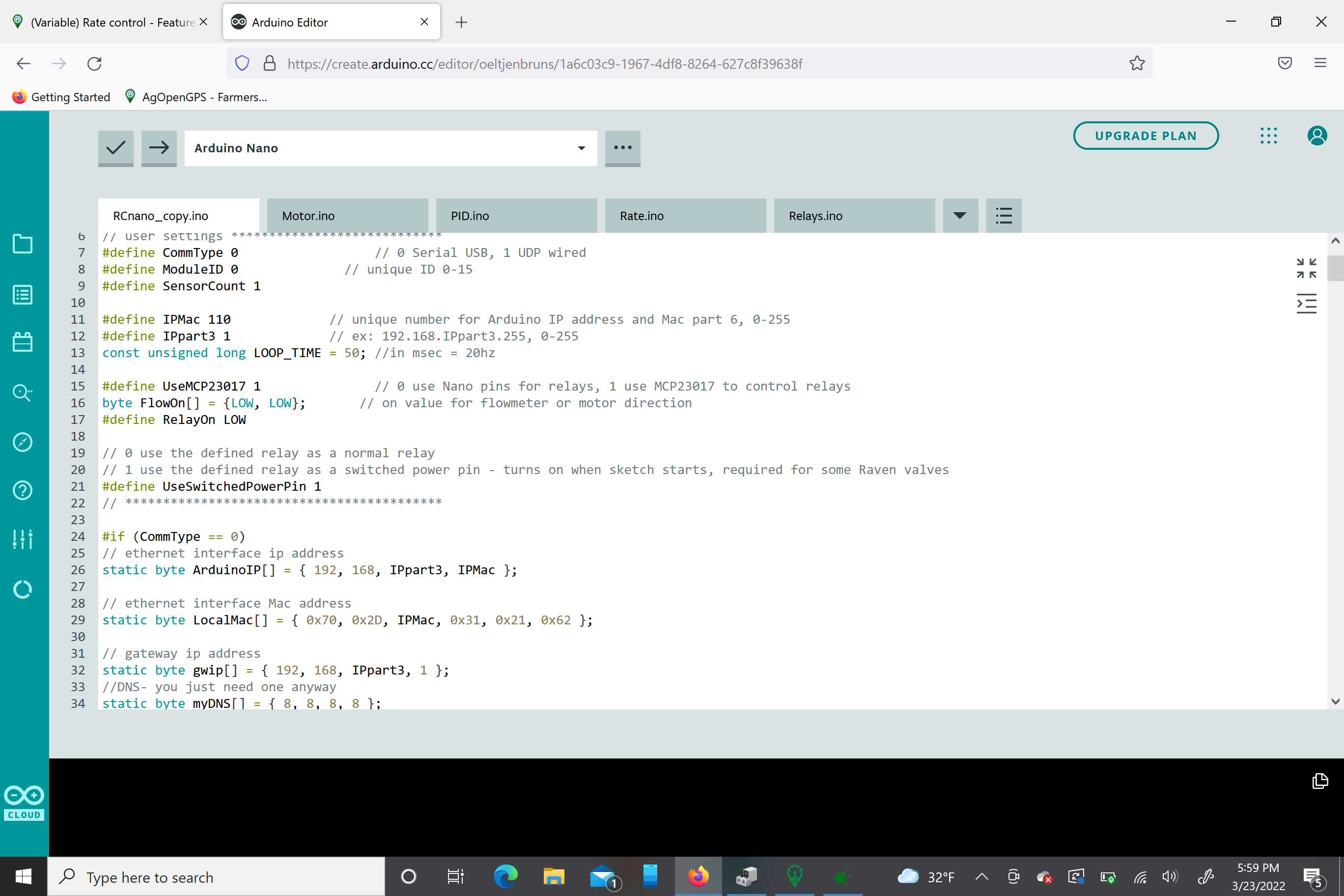
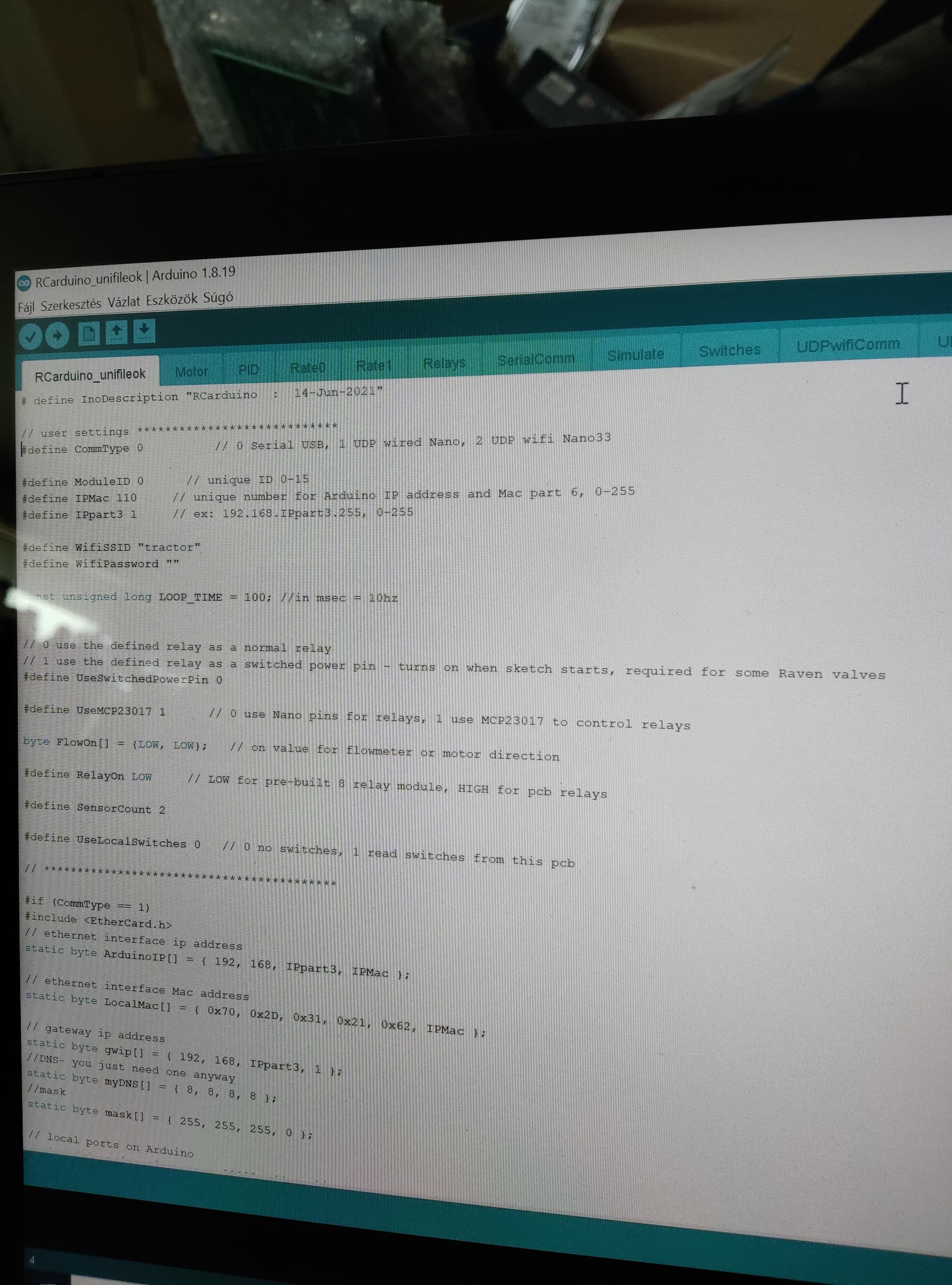
I have rate control built and hooked up with green AOG and green Mod lights on in the app window. I’m set up with 16 relay board hooked to SK21 PCB with the MCP23017. My section switches work with the simulator as Master, Auto, manual and the programmed sections with my boom switches through the rate control app turn on and off! The The RC8 board is not commanding the relays on or off and the 3 wire raven flow meter is not reading anything also. I hooked the raven to 5 volts, ground to D2 and signal to D3. I’m not sure on the arduino code for setting up correctly to control the RC8 board? The flow control control also doesn’t function unless I push manual buttons then valve moves. At one point right away, I was working at programming the arduinos and i had all 16 relays on full time. Any ideas to get the relays commanded by the rate controller? Here is a snapshot of my RCnano code. What exactly needs to be changed for values? Thank you in advance!
1 Like
Update, 12 hours later I figured out the ESP8266 Wifi board that i had plugged into the RC8 was not getting along with the serial USB that i was plugged into at the arduino nano. Unplugged the Wifi and relays came on all happy! Any ideas on the flow meter (raven part #10630172040), isn’t showing flow at all. I pinned out the 2’oclock and 6’oclock; 10’oclock and 2’oclock and there’s no voltage. I then jumpered the 2’oclock and 6’oclock signal and ground and it counted a few gallons and then nothing after that? What are the values for the D2 and D3 pins for flow meter at the SK21 pcb?
1 Like
The code looks right. The wifi board only works with an ethernet connection because the usb connection and the wifi board both use the serial pin D0 on the nano. D2 and D3 are signal connections. Each one is connected to a flow signal line, so two flowmeters can be used. For a three wire flowmeter connect the signal to either D2 or D3, ground to one of the ground connections on the pcb and the 5v line to the 5v connection on the pcb.
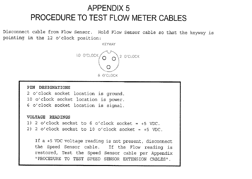
Is this the flowmeter pinout?
Is this part number a turbine-based flow meter (or spinning wheel)? Or is it a solid state, no-moving parts flow meter (magmeter)?
If I read that right, it’s the pinout of the cable that attaches the rate controller to the flowmeter. In other words it’s the mirror image of the flowmeter pigtail itself. Looks like the flow meter wants the signal wire held high at 5v with a resistor. As the it counts, it will pull that signal down to ground. Wonder if you could cut the plug off and if the wires are red, black, and white.
I think the ground was connected to D2 of the nano instead of ground of the pcb. I think that is why there was no power on the 10 o’clock pin.
I verified also with Raven tech support, your pinout is for sure correct. 10 o’clock is power 4.5-16 volts red wire, 2 o’clock is ground green wire and 6 o’clock is black signal. It seems as though the sensor is drawing too much amperage at 2 amps on the power wire with only ground hooked up. Before, when i would hook up the signal to the d2 or d3 it would start to smoke the c2 and c4 capacitors. Now I can’t even hook up power and ground to the flow meter from the 5 volt supply, which measures .6 ohms across the power and ground pin on the flow meter disconnected. I’m thinking flow meter sensor is bad? I was connected like SK21 said earlier with my ground going to the D2 pin, signal to D3 and power to 5v. It’s corrected now, thank you! Is there any code that changes what the D2&D3 pins do or accept? My understanding this meter puts out a square wave of 5 volts to 0 volts going into D2or3?
torriem, this is a turbine based meter. I’m going to try hooking up to 12 volt battery now and just test off the pcb. I hope i didn’t smoke the capacitors on the board. Any easy way of testing the capacitors? They’re not burnt at all. The temp gun showed 105 degrees at most. The 5 volt regulator is still supplying 5 volts so that part is good!
Also, the D2&D3 pins should see a square wave of ground signal or was I right by it seeing 5v to 0v signals of the signal wire from the meter? The 2 wire meters from what everyone talks about on here are a square wave ground trigger, so can the D2&D3 pins accept a trigger of 5 volts also? Or will that cause communication errors or smoke? I’m going to get a replacement right now and test the signal wire on a 12volt battery to see what it’s supplying on the signal wire!
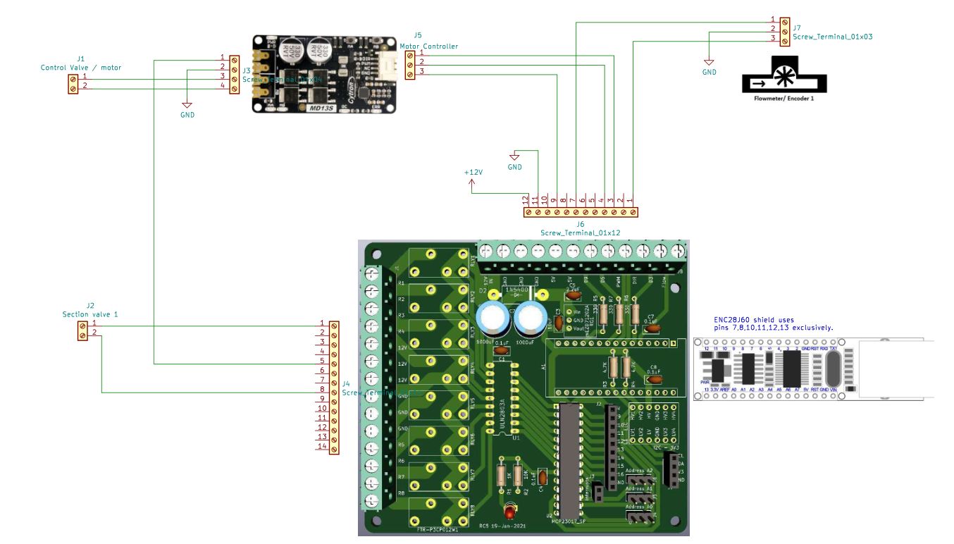
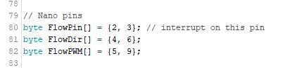
D2 should see 5v or 0v signals from the sensor. 5v is no problem for the nano pins. If you are only using one sensor then D2 is used for signal, D4 is dir and D5 is pwm. Here is a hookup diagram for RC5. RC8 is similar.
1 Like
Fixed the Raven flow control problem, SK21 was spot on with the pinout of the board! Very helpful thank you, I had questioned the motor controller from the RC8 board for the 4 wire harness as the RED wire does not get used. Only the DIR, PWM and ground. The Raven RFM15 flow meter accepts 4.5-16VDC and outputs 5-0 vdc square wave on the black signal wire to the D2 terminal. MAKE sure nobody hooks up the power and ground supply to the meter as it looks on the internet or even as the diagram above from SK21. This is a pin insertion diagram as i’ve included in my photos. Raven tech support mislead me twice to them telling me this was wiring staring at the open end face of the connector on the flow meter. I smoked two sensors and luckily Raven is standing behind there wrong doing. Thank you guys once again for helping me through!
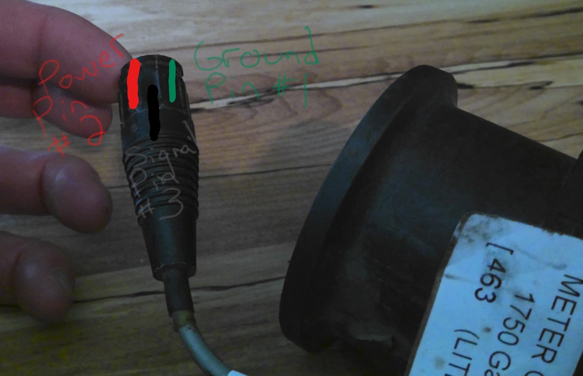
Here is the other picture as if your looking at it like in the pinout from the internet (right on Raven website).
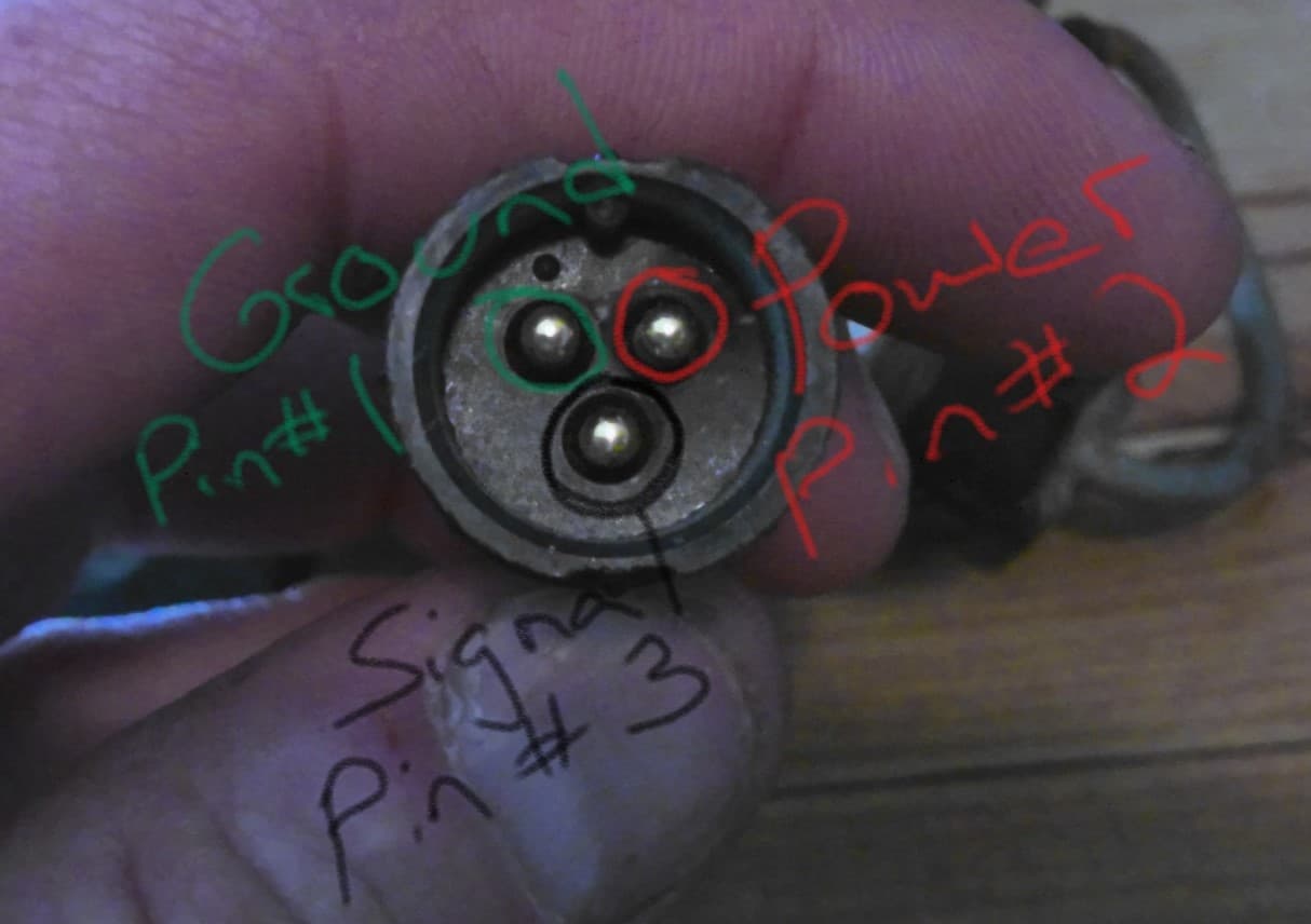
I guess Torriem was right the other diagram was the mirror image. Good thing they gave you another sensor.
the link appears to be broken ![]()
The nano pcbs are here: AOG_RC/Modules/Nano at master · SK21/AOG_RC · GitHub
1 Like

Here is a newer version of the rate app and ino file. The ino file can be installed with the PCBsetup app. Release update config, change menu, edit I/O driver file · SK21/AOG_RC · GitHub
I uploaded the new rate app and the rc nano ino file. I played with it morning, but it didn’t work. The mode is constantly red.
I tried again in the evening and it worked. I wonder why.
What do you change with module time and sensor time and min upm? My further questions are: 200 l /ha, if I want to spray proportionally, what should I set for this?
Which flowmeter do you recommend: I can buy Arag (orion) or polmac type
https://polmac.it/catalogo/en/polmac-flussimetri/rapid-check-versione-radiale
my settings: