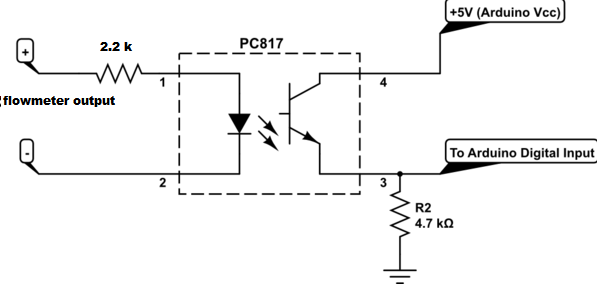
On the Arag page it shows a chart with the number of pulses per litre for each flowmeter. This is the number you enter on the Product rate page “Sensor Counts/Unit”. But I think it outputs 12V. This will not work with the pcb, it needs a 5V signal. Once you find a flowmeter, enter its counts/unit and 200 for “Base Rate”.
Hello SK21 and Kovari;
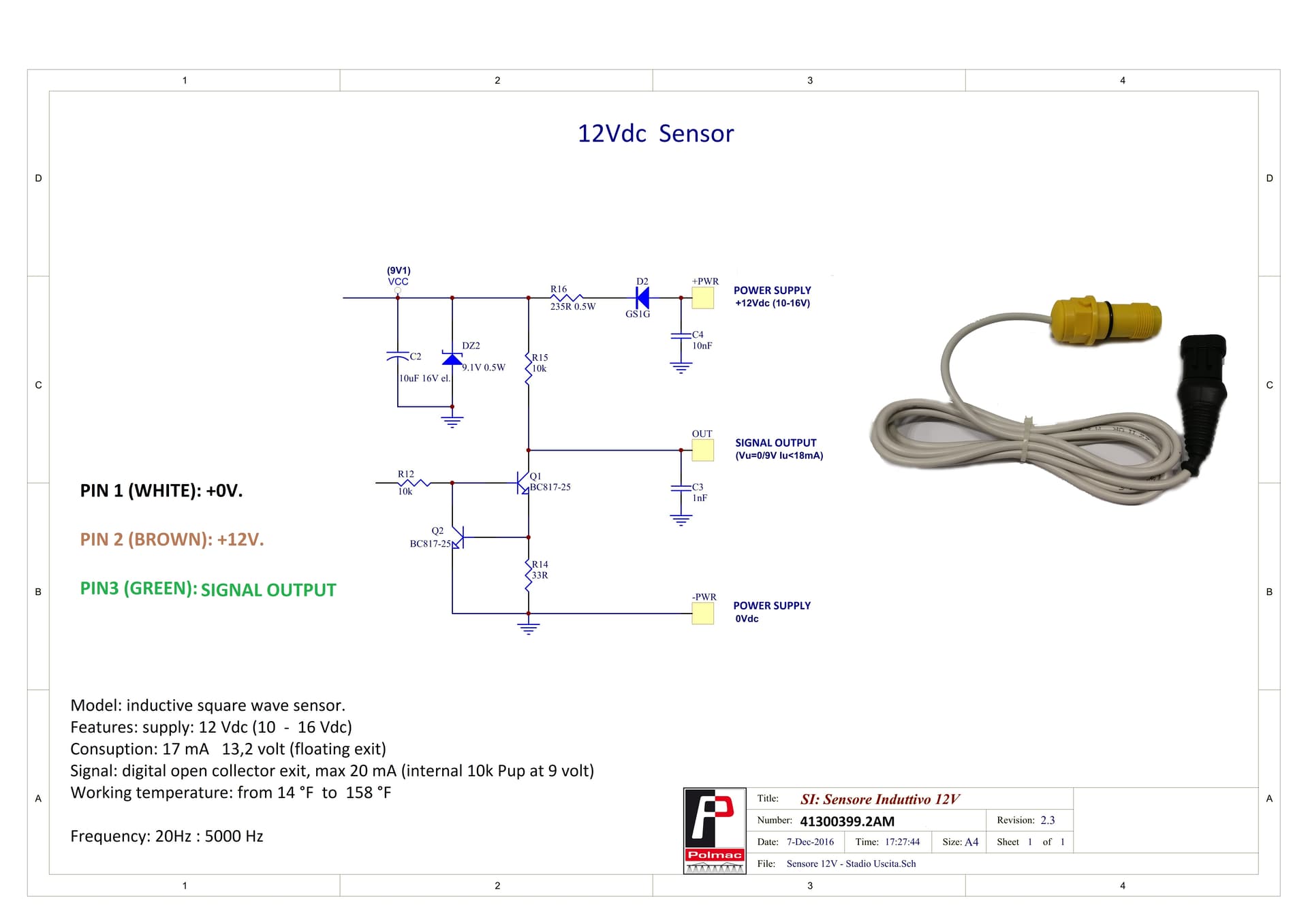
Arag usually uses 250 pulses/liter, that means 1 liter flow when it receives 250 pulses, magnetic flowmeter is 2 times more expensive than turbine flowmeters, but the advantage is that it does not need to be cleaned frequently because there is no turbine and the error rate is lower, I used both arag and polmac, magnetic and I used it with turbine, if the price difference was small, my choice would be magnetic, but the price difference is large, I am sending you the latest Polmac model that I bought and I am satisfied with, and the delivery times seem very long. I used optocoupler for 5 volt signal output in Arag, but when I used optocoupler in polmac I couldn’t get the pulses, and in polmac it worked fine without optocoupler.
https://polmac.it/catalogo/en/catalogsearch/result/?q=00375804
https://polmac.it/catalogo/en/catalogsearch/result/?q=41300399.2AM
1 Like
I installed an Arag Wolf flowmeter. The system worked well in Sim mode. I tested it at work today. When I started spraying new ground, after 5 seconds, Mode turned red. The RC port is disconnected from the system. And I couldn’t reconnect.
Are you using usb or ethernet? Are you using PCBsetup? Check the module ID # is correct. It has to be set in the nano firmware and in the rate app. Uncheck simulation mode.
Im currently assembling an RC8 PCB. I ordered the box from the BOM. Does anyone have any pics of how your boards are secured to your box? Box mounted on a rig? Thanks again to @SK21 for the design and support!
I just put a tin or plastic bottom in the box and used M3 standoffs for the pcb.
1 Like
The serial com port on the tablet did not work properly. I use it on USB. I installed another one.
I have a few questions: Which one should I change in the control type? Which one should I choose in the variable rate?

Are these values good in the conrol settings?
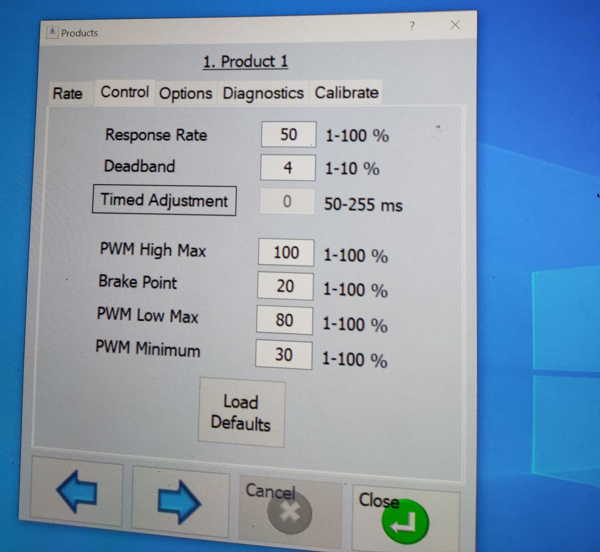
what should be the minimum upm? Which one should I use for the switches?

The md14 panel is constantly switching to one side, even in a standing position, is this normal?

Great video!
There are 3 control types. Motor - for driving a hydraulic motor to control a metering roller in granular application. Combo Close - is used for adjusting the rate and also for stopping the flow such as a Raven Fast Close NH3 valve. Standard - just adjusts the flow.
It is variable rate ready for AOG to provide the info. The code is not in AOG yet.
As long as the rate isn’t fluctuating a lot the settings should be fine.
Minimum upm is the lowest flow rate that still gives a good spray pattern. If you are going slowly the auto rate may reduce the flow rate too low. If this is a problem you can raise the minimum upm, if not it can remain at 0.
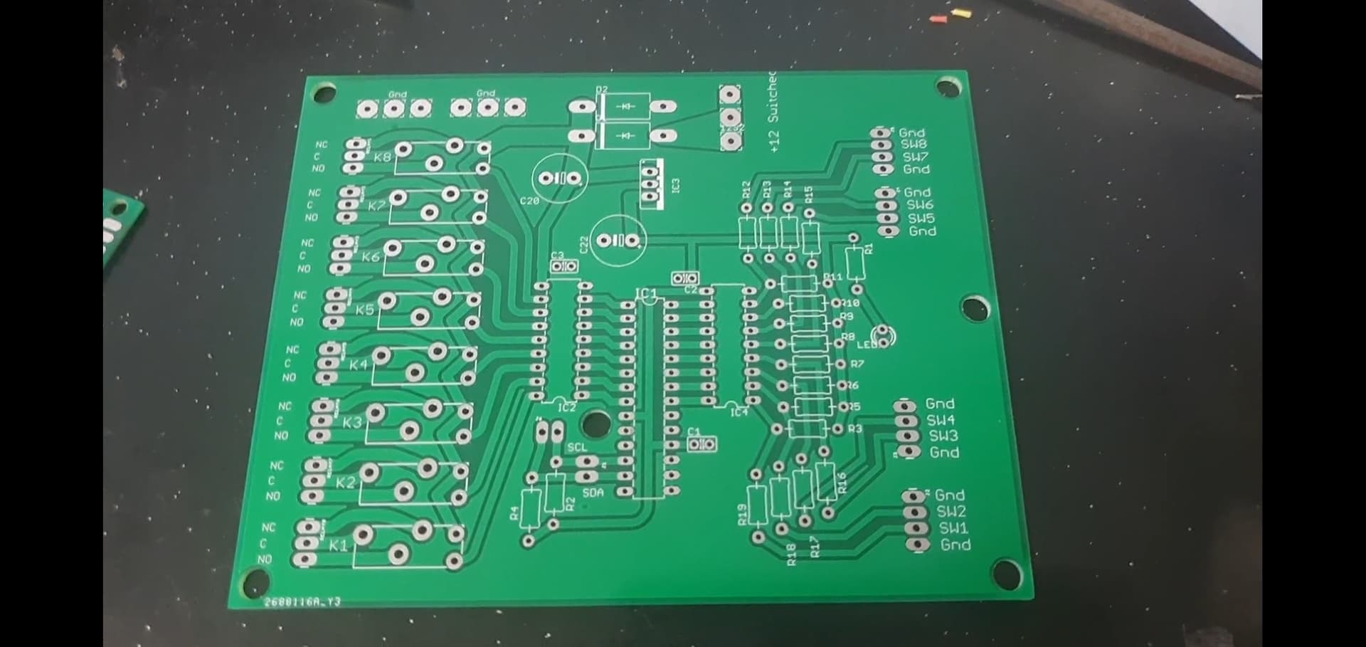
" Which one should I use for the switches?" Do you mean pcb? It is here: AOG_RC/Modules/SwitchBox at master · SK21/AOG_RC · GitHub
I am not sure what the md14 panel is.
hi,
kentSuff, how to update your program with the latest agopengps update?
I have not built it into the latent version. I’m waitingon the official big release running all UDP. I’ll make the conversion then.
3 Likes
I set the minimum upm higher, it got much better. Works well. One more problem is when I reduce the speed the pressure goes down and I return to the speed again, it doesn’t raise the pressure again. Then udp target and udp applied are almost identical. When I stop completely and then start, it raises the pressure and works well. What makes this possible? md13s cytron panel. In manual mode, when I use the sprayer without rc8, I apply the pressure manually via md13s. it would be fine for me if you don’t have the Md13 pwm signal if the aog is not turned on in the aog. I hope I have described it understandably.
1 Like
It will adjust the md13s in manual mode with the rate up/down. The code could be changed to work with aog disconnected.
As for the rate does it always fail to adjust when you slow down and speed up?
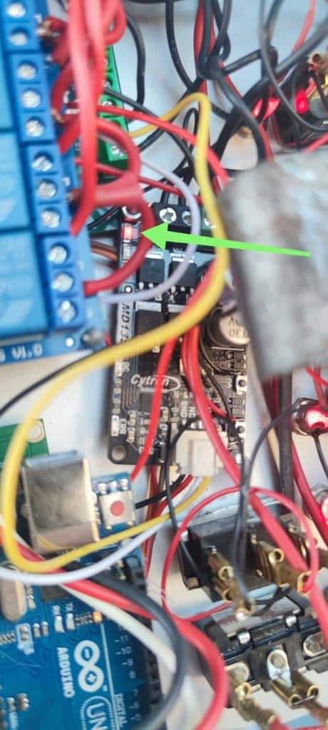
I made an Rc5 board. It does not switch on the relay board. On contacts mcp23017 always about 5v. What should I change?
Are you using the relays on the pcb or an external relay module?
I have a board from the days of AOG 3, the circuit is similar to rc5. I assembled a pc8 circuit without a relay, it does not work either. Today I uploaded a simple LED control sketch for arduino and mcp23017. everything works as expected.
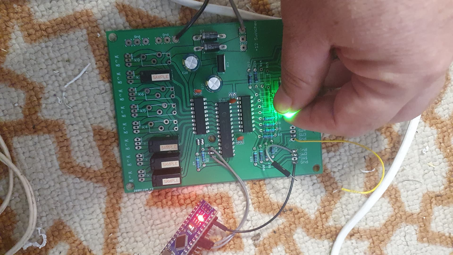
App Rate Controller started. Arduino connected to com port 3. In the rate controller app there are 8 sections of 200cm each, in the diagnostic window I see how the image of the sections turn on and off but the relays themselves do not react
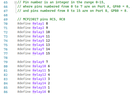
Are the MCP pins defined to match your pcb.
When the sketch starts does it say “Starting I/O Expander …” and “I/O Expander found.” ?
I uploaded sketch as is. I/O Expander not found