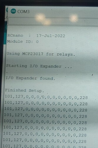
itc_scanner show me 0x20. I load rcnano.ino again, turn on the power and all the relays turn on. But there is no other reaction. can’t turn them off.
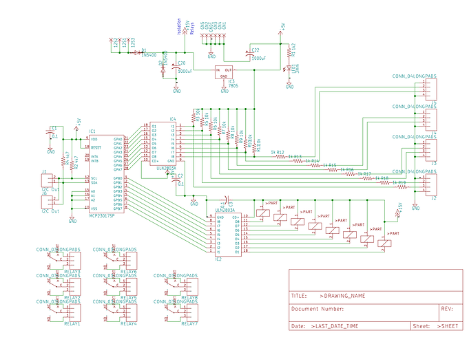
Is this the schematic for your pcb? If so I think the mcp pin numbers are correct. Try going to the diagnostic page and pressing Master On to see if it helps.
Thanks, unfortunately didn’t help.
I had problems also. ended up finding a post online somewhere that I needed to add the following and it works.
#include <Adafruit_BusIO_Register.h>
#include <Adafruit_I2CDevice.h>
#include <Adafruit_I2CRegister.h>
#include <Adafruit_SPIDevice.h>
Here are some files to debug RC.
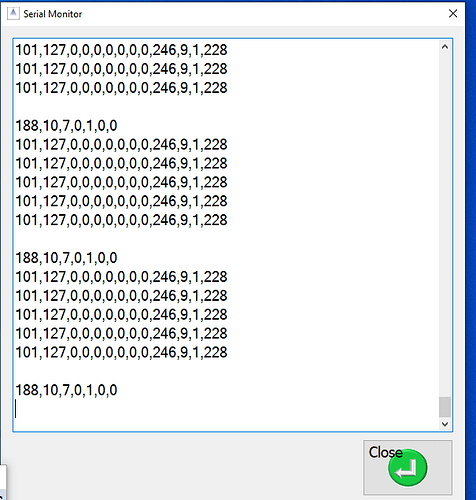
The app has a new menu item, serial monitor. Upload the test ino file, run RC and AOG in simulator. Turn the
sections off and on with the manual section button in AOG. In the serial monitor window of RC you should see the line 188,10,0,0,0,0,0. The third value should change from 0 when the sections turn on. This proves the pgn is getting through to the point in code where the mcp should activate. To stop the serial monitor from scrolling click anywhere on the screen.
Thanks a lot. Works great now
Glad it worked for you. Every once and a while I get lucky.
I am using the SK21 application to load the code and everything works.
Thanks Ray. I will add it to the nano code.
Hello, to perform a dose calibration with an electric motor which throws fertilizer into a seeder, how do you do it? Is there a motor test to know the minimum pwm?
Thank you!
Gday, I am at the point of trying to get the flow meter on my set up working, and have the Arag flow meter, I have used the above diagram adding resistors to an optocoupler, for the 12v - 5v issue, it seems to be working though it does slowly count up when there is no liquid flowing, the flow rate goes up when there is flow, so I’m guessing I need some more resistance somewhere in the circuit? Any ideas?
Never mind, I found the issue was with the D2 pin and the Ethernet shield, once I removed the pin from the Ethernet shield I got my flow to work using the logic level converter. Now onto trying to sort out the settings so it will hold a set flow rate.
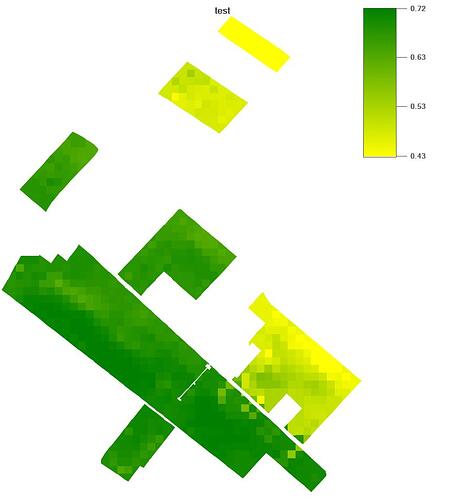
can someone explain to me how the rate control works. I have a shape card with more and less to come up with. how do I fill that in the rate app. or can i transfer the card like this. it is a shape file.
see photo as an example
There is currently no support for shape files. There may be something in the future.
how does the rate control work? adjust the machine with speed via GPS. or in a different way
Yes it adjusts the rate based on speed and working width. It measures the flow and adjusts the rate to match the set flow rate.
I’m not sure what jdros exactly asked but isn’t the “variable” part of aog variable rate control adjusting application rate based on a map. The map giving different rates (as in litre or kg per hectare etc.) for different parts of the field.
Yes it is. The mapping for variable rate hasn’t been added to the current aog release.
Thanks for that, I have followed the topic a bit but don’t have tools that would use it. Didn’t know about the aog release status.


