Looks to be a better option than a WAS set up. My last linear WAS got damaged which i was gutted as it was not cheap. I will be looking to get this installed to my tractor. Take it will work with the V4.5 micro board?
Tthis is how it will work, my code on git matches exactly to 4.5
tm.zip (25.9 KB)
1 Like
Thanks! This helps me to understand the o-ring channel much better!
Am I right in thinking that you are not screwing in the connector but instead mounting it from the outside using epoxy? That would seem like the easiest approach.
Andy
I’m making threads for the M12 gland, and M2 for screwing the TM. There’s no need to draw the thread on the model; when creating the CNC program, the appropriate tool will be used and the thread will be made.
1 Like
Ahhhhh! Nice. I like that. It makes things a lot simpler. Andy
This sounds amazing! Should really simplify the installation in new equipment.

6 Likes
And to which pins do you wire the imu to the v4.5 board?
1 Like
Is there a version for KEYA?
I started this modification today based on the pictures on your discord, and am using a spare AIO 4.1 board with a BNO05 for some testing.
I do have a board that is for dual antenna gps and does not have an IMU on it currently. Do the same modifications have to be done for all boards as well as the Teensy (Code wise)? Might be a silly question but I’m soldering away on these tiny posts and it’s something else.
I ordered the TM171 based on what I read above and I have a few BNO085 lying around. I seem to have the Teensy Identifying the UDP from the monitor in AOG but I am only seeing PGN 253 and no 250. I have the BNO wired up correctly (from what I read here: https://discourse.agopengps.com/t/agio-autoconnect-usb-sensor-fusion-dual-heading-w-o-arduino-esp32/8479/3 but I am not getting anything on the steering monitor.
What step did I miss here? I also notice there is a spot on the board that says “RVC MODE: Solder for RVC” and I hadn’t soldered that yet, wasn’t sure if that was necessary or not.
Thanks
1 Like
Please give me a version for KEYA motor
Yes, in RVC mode, you need to cut the two tracks designated for this purpose and solder two pads, as described on the board. On the BNO you’ll use as the WAS, connect P0 to 3.3V to enable RVC mode. It must be connected to the appropriate UART pin defined in the Teensy code. Serial3 (pin 14 -Tx3) is available, so you can simply connect pin 14 and SDA of the BNO.
There is no version for keya
Perfect, okay I will go about soldering that trace and cutting the other. On the AIO board, I used your examples from the Github and soldered pin 1 to 11 on the backside of the ampseal connector, as well as the other connections you did in the pictures. it looks like they are BNO ground is going to pin 12 of ampseal, and the way I had it soldered currently (according to the pictures on the guthub) Teensy P15 is going to P13 on the Ampseal. to which I have nothing connected to at this point in the harness.
I must have messed up my soldering here, so should I move that blue trace in my picture to P13 of the teensy?
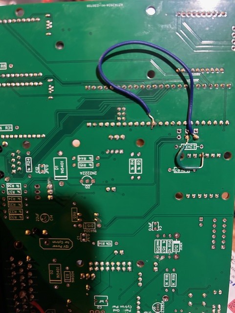
That’s fine. You can also connect RX3 directly to one of the free pins on the 23-pin connector.
Autosteer_gps_teensy_v4_1-WAS.zip (57,6 KB)
I modify code for KEYA - not tested on tractor, on the desk it behaves like an electric motor
Serial7 = GPS
Serial2 = TM171
Serial3 = TM171 WAS
If serial3 is connected read angle from TM171, if not read from analog sensor
5 Likes
Awesome, thanks for that. I managed to get the wiring all sorted I believe and am sending the SDA data to RX3 on the teensy.
A new problem has came about, and now the UDP / ethernet seems to be shutting down and not even coming online… Unsure of what might be causing this but I have flashed the board twice with the same program, and attempted resetting the IP for the connection, as well as just plugging it into the complete board that had the standard teensy program, and it connected to that.
Any ideas on what i messed up here? I am going to try the TM171 as well and see if i get the same results.
Send me the code you are uploading, I will check if it works correctly on my board.
Tried both of the following programs:
AIO_v4_FirmwareWASBNOkorektaBNO.zip (49.1 KB)