“PS0” must be connected to “VCC_3V3”. In your case, a solder joint on the jumper associated with PS0 will do that job.
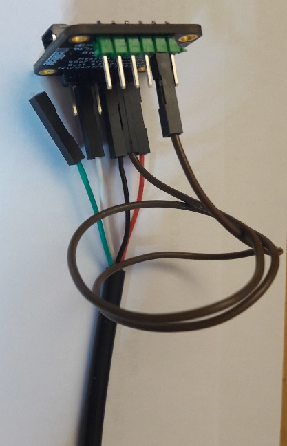
It’s a 3.3V-only board, so be sure to use a Serial-USB-cable with 3.3V supply output. When using a simple cable like this, just daisy-chain a red LED in the supply line of the cable. Connection is like that:
“GND”: GND (often a black wire)
“SDA/MISO/TX”: RxD of cable (often a white wire)
“VCC_3V3”: supply like descibed above (often a red wire, mind the voltage!)
That’s all. After that, you can check the data flow with any terminal program like HTERM. Setting is 115200 baud, 8N1.
I don’t recomment cables based on CP2303 clones, because Win10 is causing trouble and don’t use CP2303 originals, because Prolific is the reason of that trouble. For the same reason, avoid FTDI cables. Suggestion: CH340-based cables like shown here with an Adafruit board (has an onboard voltage regulator):