This is the version that should work on the v4 board in all combinations. Keya/Cytron, 2xTM/2xBNO/TM+BNO/TM+analog/BNO+analog
Tested on the table so far.
Serial7 = GPS
Serial2 = TM171 IMU
Serial3 = TM171/BNO WAS
Serial5 = BNO IMU
If serial3 is connected, read the angle from the TM171/BNO; if not, read the angle from the analog sensor.
AIO_ALL.zip (340,4 KB)
1 Like
I have some questions about this system:
Which pins on the Tensy do serial3 correspond to? Do these pins have direct communication with the 23-pin ampersial connector on the AIO 4x board?
Another question is, if I use a BNO085, can I make the communication directly from the SDA and SCL to the Tensy, even with a wire distance of 2.5 meters? (With the little knowledge I have, it seems that this will not work)
I really didn’t understand how this part works. Or maybe I’ll need a Qwiicbus board to make the communication?
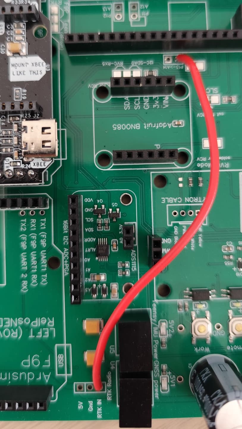
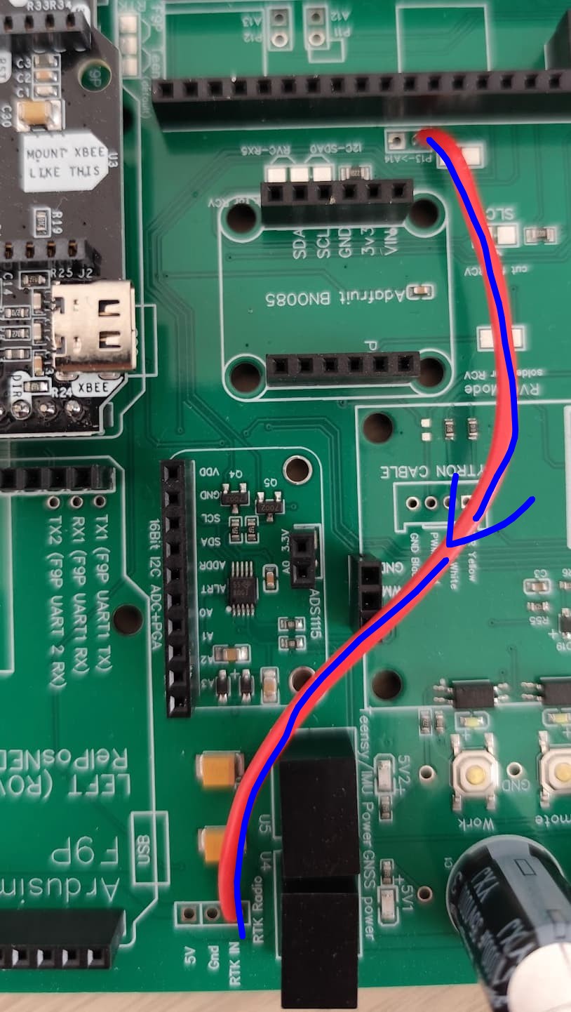
There are three free AMP pins on the board - you need to solder a cable from serial3 (RTK Radio) to P11/P12/P13.
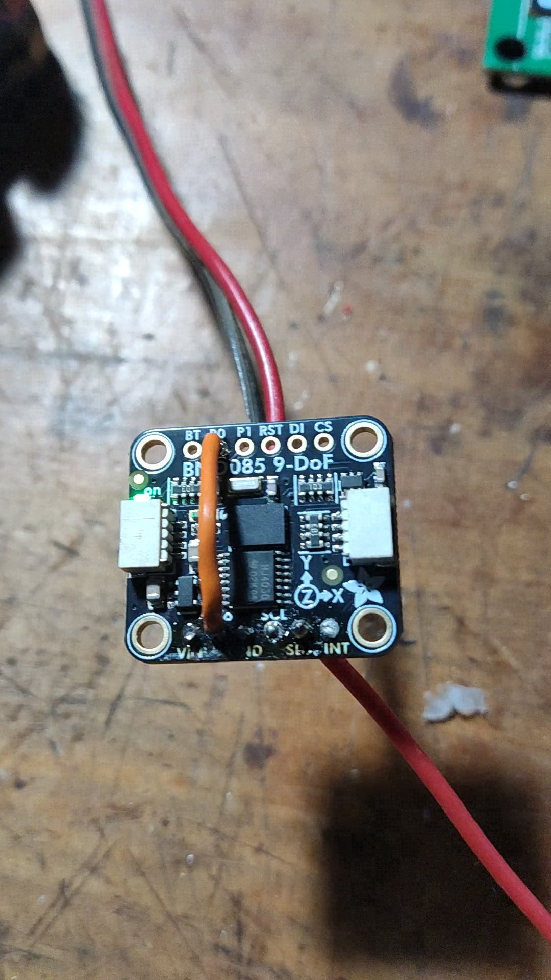
In the BNO, change it to RVC mode(connect P0 to 3.3V). Then you have SDA pin for TX.
I figured out how to transform the BNO085 into RCV mode; would it be done as shown in this image?

To power the BNO, could I use the same cable that currently powers the wheel sensor?
VCC 5V
GND
And I would use the signal cable from the sensor to the SDA/TX, should that work?
I didn’t quite understand the part about connecting to the Tensy. Can I connect the SDA/TX that returns from the BNO directly to a pin on the Tensy? I know that the amp23 connector has 3 pins that go directly to Tensy pins, A12, A13, and A14. Can I use one of these for the SDA/TX return?
You can use the 5V and GND from an analog sensor.
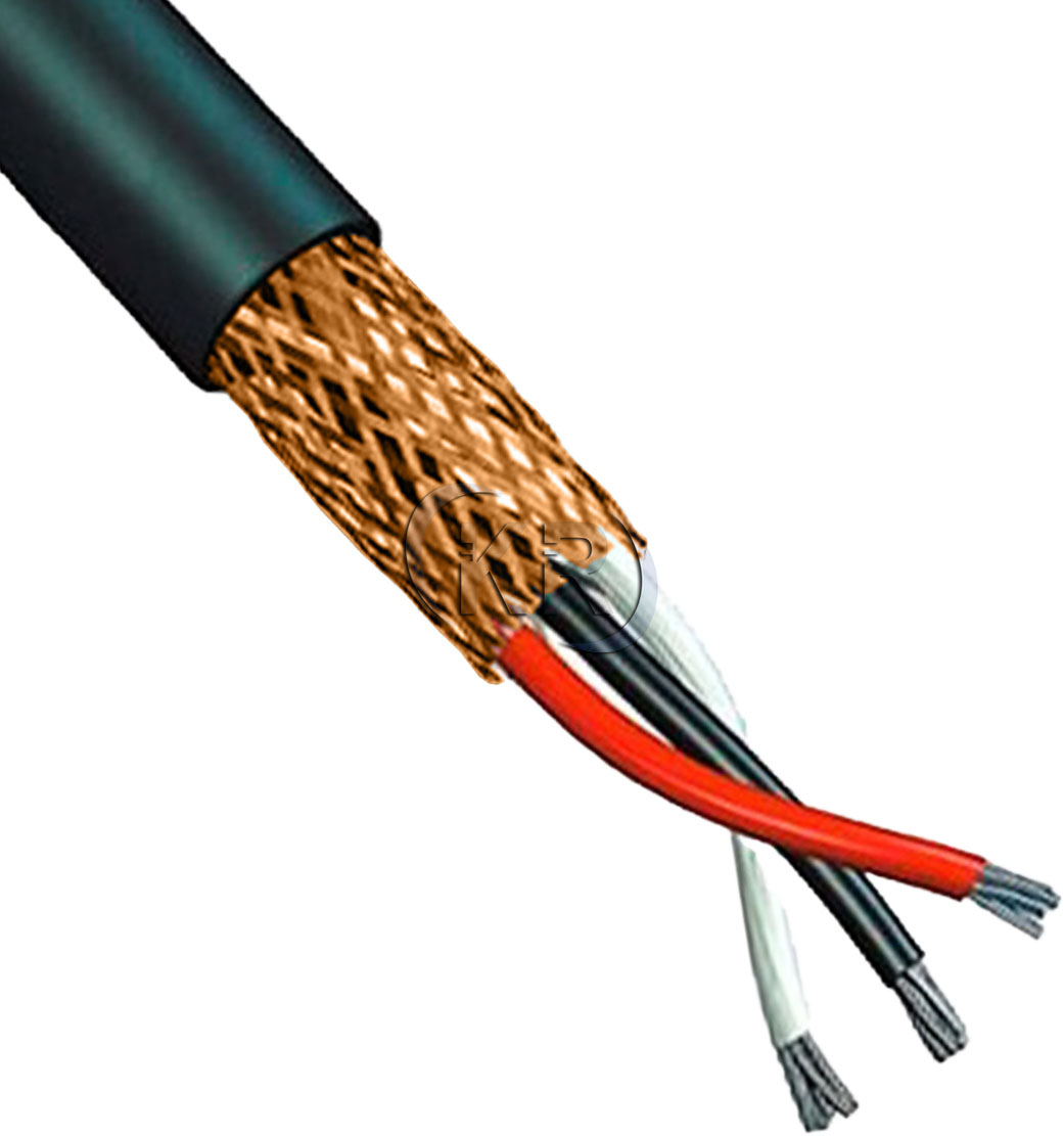
The cable should be shielded – you can try one, but you might encounter problems.
You can do something like this and connect to p13:
I already use a shielded cable for WAS, similar to this one:
It’s not possible to directly use the connector pin that provides access to the Tensy pins to connect the IMU’s SDA/TX signal? From the photo you sent me, how does the IMU signal reach that RTK in pin?
P13 connects directly to P13 on ampseal plug,
Serial 3 is the RTK radio pin
So let me see if I understand correctly, using this image as a base, the signal enters through the ampersial connector and goes to that P13 pin next to the Tensy board, and from that pin I make a connection to the RTK in pin, which is Serial 3?
If that’s correct, I understand now.
I was confusing things; I thought I should supply the IMU signal directly to a pin on the Tensy board.
Yes you are correct, the rtk in connects to the teensy
1 Like
Today I had time to work on this. I used the code you provided, but it didn’t work. The wheel sensor values were unstable, and the tractor wheels were spinning uncontrollably within the application. I’d like to add the video here, but I couldn’t.
I used the code that’s outside the macOS folder; I couldn’t write the code inside the Tensy folder using Config o Matic.
The IMU on the board also didn’t work. Do I need to switch to RCV mode as well?
Could this be causing the problem?
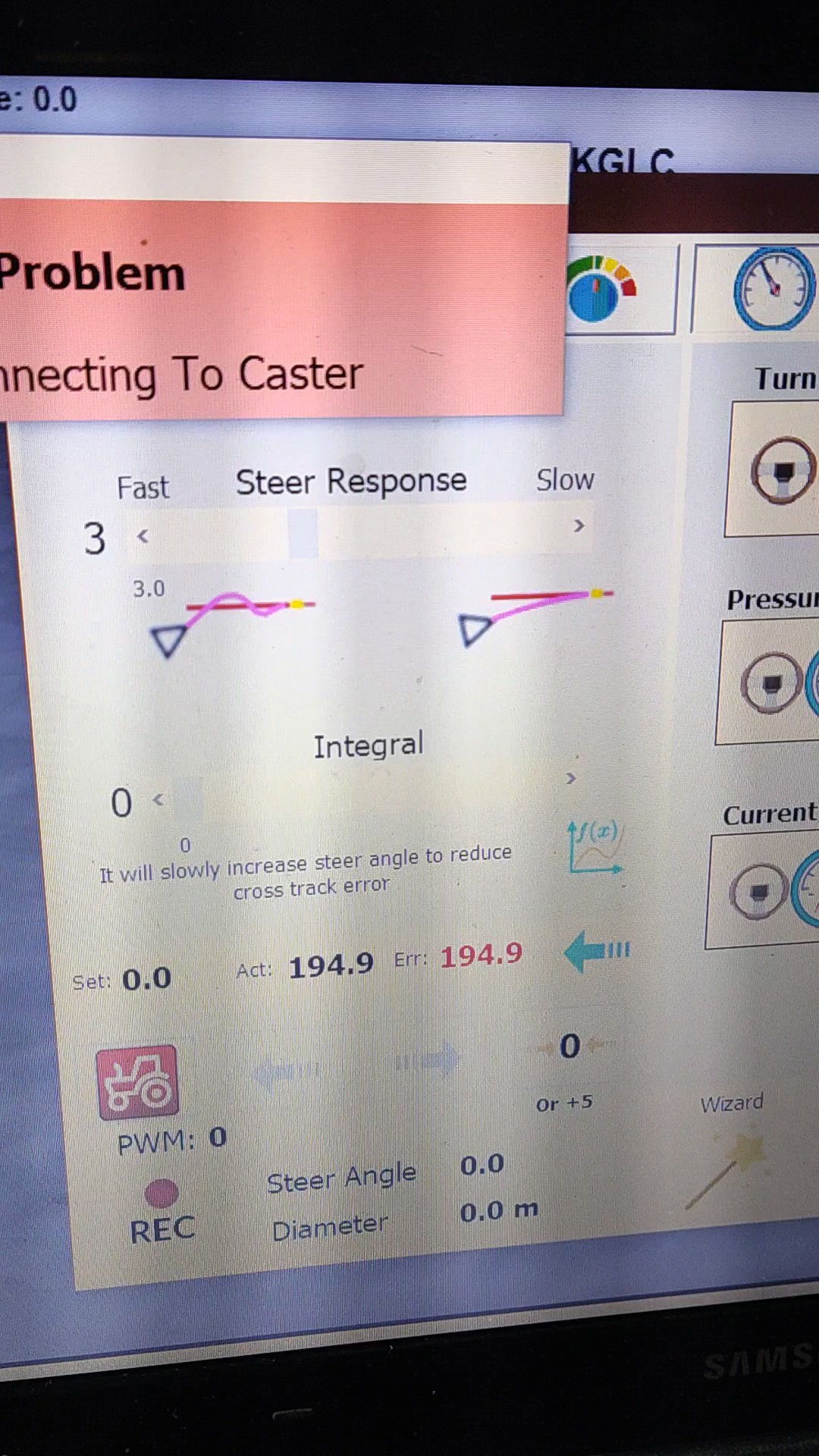
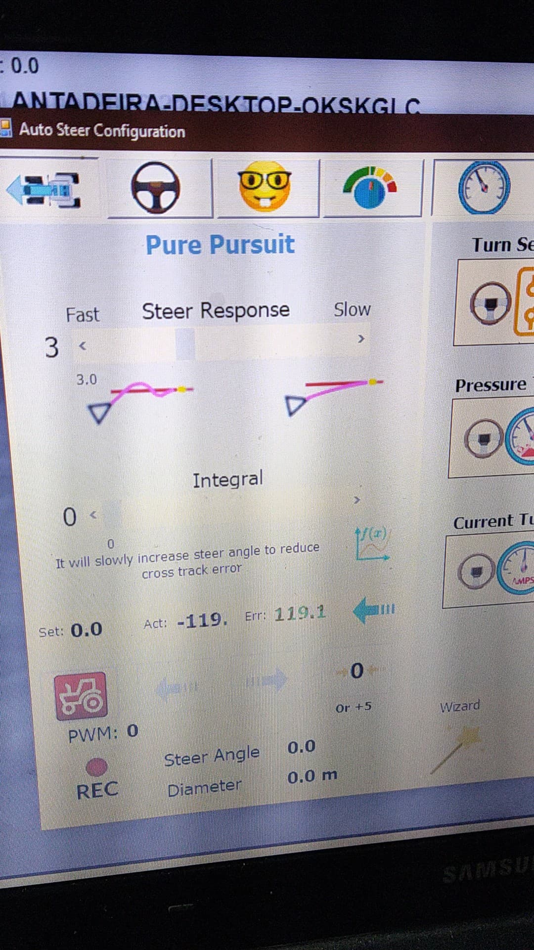

yes, BNO on board should be in RVC mode.
And how do I do that?
Do I need to solder that jumper
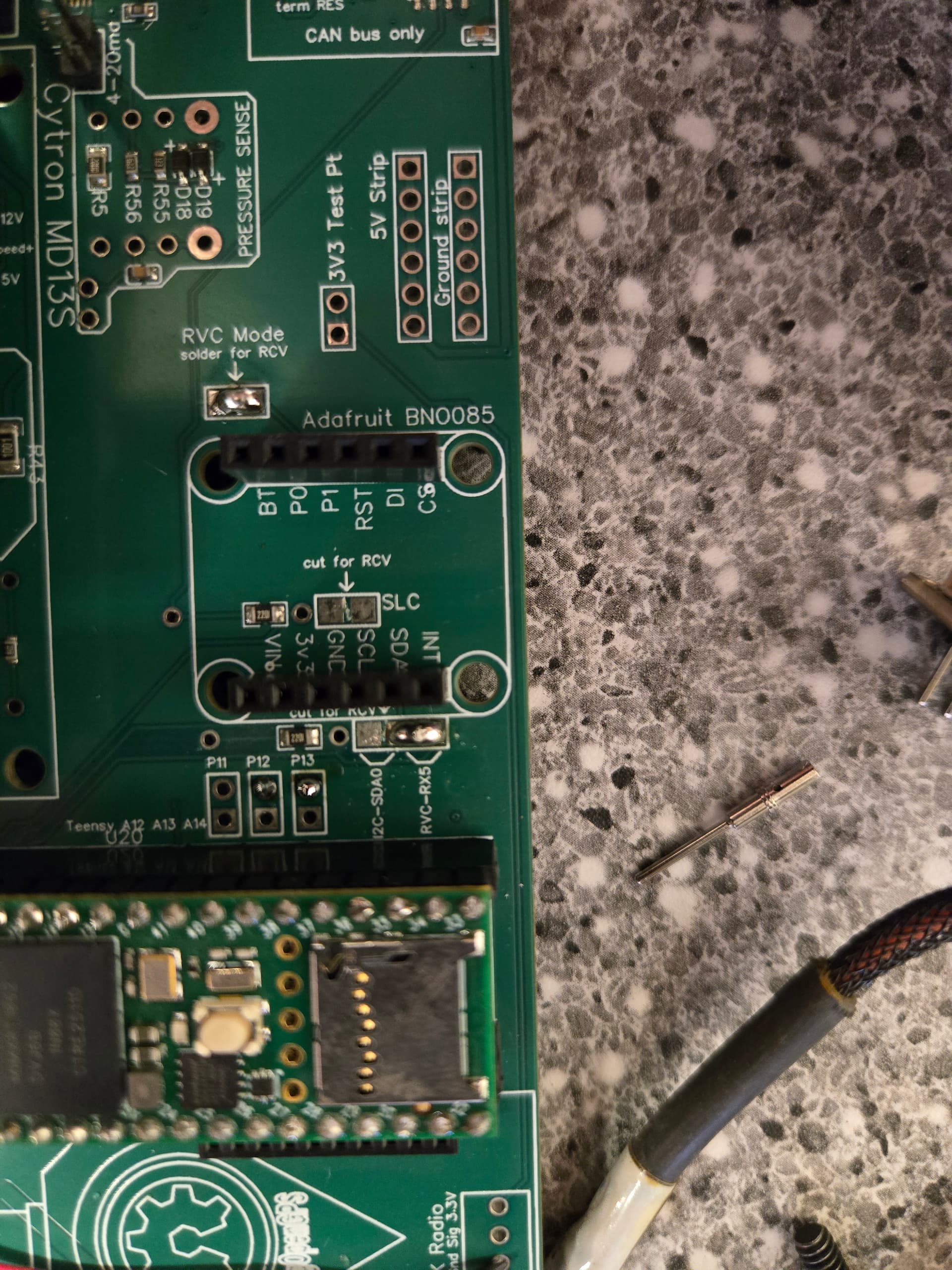
and connect the 3.3V to the PO ?
Do I need to do anything else?
can TM 171 be used as IMU in ONLY CAN PCB?
what kind of material should be used for this?
@mat Today I tested the tractor with this system and it worked partially well, but I have some questions.
First, if I turn on the GPS with the tires turned, it will show up on AgOpen with the tires at zero, and therefore I can’t use the autopilot. How can I easily reset the steering without having to restart the system?
I also know that it has a system that automatically resets the sensor. Under what conditions does it perform the reset?
Another question is how do I configure the counts by degree and Ackerman? I tried to configure it as if I were using an analog sensor and ended up messing everything up.
Another suggestion is that, to use the Keya motor, the ammeter that turns off the autopilot when holding the steering wheel by hand is not working in this Tensy configuration you provided.
I’ve improved the KEY load for disconnection.
With the IMU as WAS, you should run it with the wheels straight. There’s a WAS reset option, but that would have to be done every time.
With 2xTM171 CPD and Ackerman, I configured it as with a standard sensor, and it worked.
After some thought, I improved the automatic zeroing feature. Now, the WAS will always zero automatically. When the angle error is large, simply drive a short straight section with manual steering, and the WAS will quickly reset to zero. When the error is small, the corrections are small, according to the conditions set in the code. This completely solves the problem of wheel alignment with a large accidental error.
@baraki This will be very useful, thank you for keeping the system updated. @mat Now I just need your help to make the code available for use with a Keya motor and, if possible, also the disconnection part when a load is applied to the flywheel.
Does this code work for BNO085 as both an IMU and a wheel sensor, on the AIO 4.5 std board and Keya motor?
Is there firmware to use on v4.1, um982 dual, cytron phidget, and imu for was? Thx