I think I have everything wired correctly, at least I believe I have … I have the TX of the TM171 on the knuckle running to pin 15 of the Teensy, which should be an RX. It looks like the angle sensor is auto zeroing, i believe like it is supposed to… but then this seems to make a mess of the calibration process for auto steer.
When i go through the calibration process for auto steer, that’s when the numbers get all sorts of wonky… Did you have a similar issue?
In addition to the lack of roll and heading, I’m starting to think that maybe the GPS software itself might be off. The tractor is only facing one direction, no matter which way I turn.
One thing to note is that hitting the red PWM button when standing still wrongly auto zeroes the was. This is, because when you hit the button, it assumes a speed of 8 km/h, and since the chassis imu doesnt move it auto zeroes the was.
When you have wired it up correctly, the displayed actual wheel angle should change according to the real wheel angle.
Keep in mind that starting the board sets the initial zero was, so its advised to keep your wheels straight before turning on the board.
do you have good gps signal? Roll only works with a good signal.
Okay, so I took it completely off and triple checked the wiring from sensor right through the board, including my mediocre soldering job on the reverse side. I have TX from the Knuckle TM171 going through to RX3 on the Teensy currently. Sensor is zeroing out properly (from what I can tell) on start up, but occasionally jumps around to 264 or a random large number. I do notice that my sensor is not quite perpendicular to the tires when straight, so I will adjust that tomorrow morning to see if it works. Also running the program with Test ending in it.
The there thing I am thinking (may be nothing of importance) Is that I set up the AIO board for a BNO WAS running in RCV mode. So made all the necessary cuts and soldering. Would this have any effect on anything? I am using a BNO085 as the IMU on the AIO board.
I was getting RTK fix, as far as I can tell. I have run single Antenna on the Original Teensy program (Not and of these modified versions) and the IMU was reading tilt. I haven’t been successful with the dual set up so far which is driving me a little up the wall lol.
Did you flash the correct firmware and configuration for both f9ps (assuming you use these for dual)
I reflashed the two F9P’s, tested both in Single with original Teensy as well as flashing them each with the Dual configurations, on the Original Teensy program I get tilt from the antennas (with Dual). So currently the only way I am getting Roll compensation (or at least and indication of it on the screen) is when I run the original Teensy 4.1 code.
When I load one of the other programs for the modified code with this WAS system: I lose the roll compensation completely, Tractor visually on AOG does not rotate when I turn, nor face the direction I am moving correctly. The TM171 on the knuckle is also giving me trouble too, but could these be related? I may try and make the sensor run more parralel ( horizontal) to the direction of travel tomorrow, but I’m not sure that would help.
I feel like this is something within the code itself possibly? Or again, something with the wiring on the backside of the board or the RCV conversion I did on the AIO board for the BNO085?
My board is a 2.4. It is different than the pictures so it makes it hard for me to know what to do. Both of my BNOs are on the mounted to the board itself so I don’t need to make the connections to the 23 pin connector. On my WAS BNO I have made the connection to power, ground and 3rx on the processor. You mention cutting two leads. What connections are you removing? I did unplug my mechanical WAS so that it’s not feeding the board with that data. Do I need to do more?
I was just cutting the traces for RVC mode. I’m not familiar with your board to know if there is something to cut. On the v4.5 it tells you where to cut and solder for RVC mode.
What housing did you use for your axle bno?
There is a file further up the thread that I had 3d printed.
Hello everyone. How should the bno085 be connected to the wheel?
To which pin on the bno085 which is on the wheel, connect the board wires from pins 11,12,13
Hi, the IMUWAS with UART communication can sometimes freeze (regardless of whether we’re using the BNO or TM171).
The UART communication itself and the long electrical cable are probably to blame.
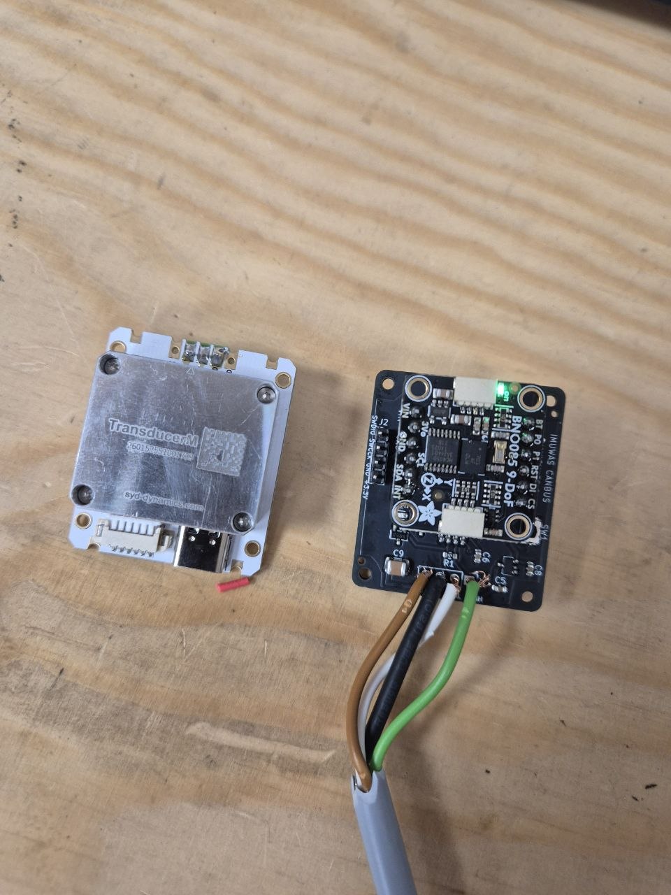
Yesterday we received new adapters for the BNO085 with CAN communication.
We’ll let you know how the tests go soon.
Video in telegram group ![]()
2 Likes
How will this work with the aio boards with only 1 canbus if you using the keya canbus or CANBUSEnable valve firmware which is also using the 1 canbus on the board
I immediately added an additional CAN transceiver.
But it’s possible to run the signal on the same CAN bus.
Hello, how did you solve this problem? I don’t know what to do either.