All about the main settings in AgOpenGPS
UDP Settings:

These settings normally require no change since they match the settings in the individual Arduino modules.
If you do not need ethernet - uncheck udp.
This is used to send Nmea or commands from the arduino to AgOpenGPS.
For example on the bd982 receiver enter the ip of the computer with port 9999 in the settings.
Ntrip client:

This is used to get rtk correction from a ntrip server and send it to the rtk receiver.
GGA Interval:
Some providers like VRS Systems (Maschinenring, Sapos…) need your position. without your position they are not able to send you data. here you can set the time how often you send back your postion.
With use manual fix you can send back a fake postion (always the same). with that you could not be tracked by the nrip caster.
to udp port: leave it at 0 when using usb/rs232 connection.
Ports:

GPS Port:
- COM: The source of you gps receiver
- Baud: the speed of the connection
- Nmea hz: the speed of your receiver (how often he calculates your postion/sec)
- Fix From: Some receiver send gga and some rmc format ( ogi is something special)
- Nmea String: here you can see data from gnns receiver. should look like:$GPGGA,083210.00,4651.2145576,N,01536.0105240,E,5,12,0.9,300,M,46.9,M,53
$GPVTG,0,T,034.4,M,1.9,N,3.5188,K6C
Autosteer Port:
is the connection to the arduino which does the steering and/or section controll and reads the sensors for heading and roll
JRK: you can connect a pololujrkg2 controller via usb to this port if you enable this
Section Port:
a second arduino of you need more connections for relays.
IMU Settings:

Roll Source:
- From Autosteer: means that you can use a mma8452 or a dog2 connected to the arduino to get roll
- Brick v2: roll is comming from the imu brick v2 via usb. you need to setup brick and insert IMU Brick v2 UID
- ext UDP Source: data is coming via wifi/ethernet
- from gps: using a dual antenna providing nmea string for roll (trimble, ub482)
Heading Correction Source:
same as above. paogi is a very special to reach users…
Roll Zero:
is used to 0 the roll in agopen
Gps Heading From (where is the heading comes from)
fix: calculated by agopen using fix to fix distance (looking back in the past to generate heading)
gps: heading is taken by the gps receiver
hdt: heading comes from a dual antenna system (extrem accurate!!) via nmea

The steer chart displays the actual reading from the wheel angle sensor and the setpoint by agopengps.
you need to setup the wheel angle sensor before in autosteer settings.
Vehicle Settings

Turn Radius is needed for calculating the radius for self autoturn
Hitch Lengh if you have a rigid tool that is the point where the tool is. for trailing its the hitch length

Distance is the length between rear axis and the gnns antenna
Offset is used to move the antenna (if need mounted in the center)

Turn on Ahead and turn off delay is used for automatic section on/off
With tool Offset you can move tool to the left or right

Min Unapplied
Section Turn Off below

With Snap Distance you can move the guidance line to the left or right
cm per lightbar pixel
auto/manual autosteer

Workswitch enable
Andreas , this wiki is very useful to me : you explain very clearly the subject
But there are many differences with the 4.3.10 version of AOG
In your doku Wiki ( gh-ortner.com ) you indicate to click on the "steerWizzard " : I do not see it anywhere .
Is it still necessary ?
Is there a video focused onthat subject
Many thanks bruno
You have seen the manual in AOG ?
Maybe not in your language.
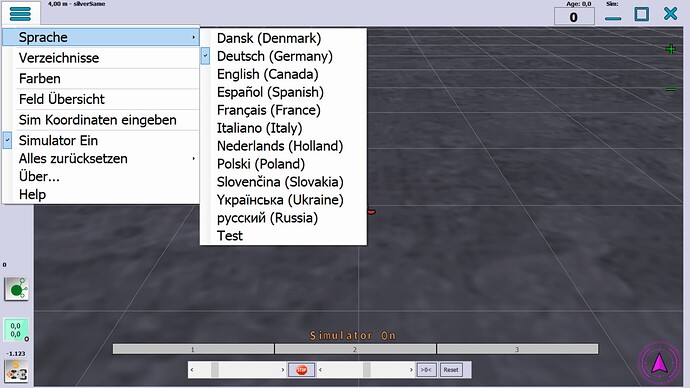
I normally use danish but just checked if german was there.
Many videos (youtube icon at top right in this thread) i suggest this only half year old: AgOpenGPS v4.6 Beta Test, or when you have that one you might also find this one but it is 1 year older: Setting up Autosteer - Hardware & Software - YouTube
1 Like
thanks Lars, I began to understand
My problem is that the WAS do not ,although it has 5v current and sends a signal , I have no response in the autosteer config window.
I have to see why the pin of the arduino seems not to have the signal (of the WAS )
is that correct ?
bruno
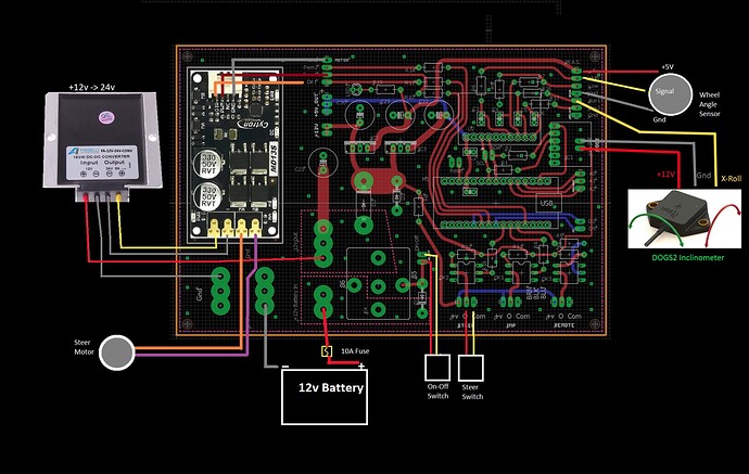
Oh I am afraid you use wire diagram for ver 4. In ver 5 was goes to the ads 1115 . You must use diagram from support folder that comes with download of ver 5
Lars,
I had to use Ver 4.3.10 with the .ino that comes with ( autosteer-usb4.3.10 ) :cause I could not get the “new” BNO0085 quickly enough .Otherwise , I would have preferred the ver 5 .
My choice is : PCB v2 + MMA + Cytron + Ads1115 + heading from fix to fix and the heading correction from autosteer
Plus the arduino F9P base + rover that works perfectly .
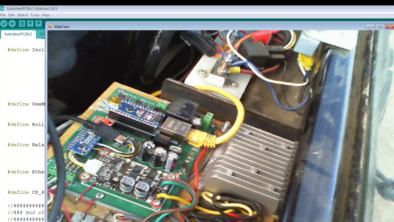
I send you the schematic I used to solder the PCBv2 : seems to me the good one ? , I downloaded it on Sept 2019 for further information .
For the moment ,I found that the "information " of the WAS does not arrive to the Cytron
Stuck somewhere near the arduino nano
any idea welcome !!
Bruno
Ok so you have was connected to ads1115, then I guess ads1115 is faulty.
Do you get the roll in from mma?
Yes , I get the roll and the heading from gps , the fix ,
What if I disconnect the ADS1115 ?
and modify the arduino conf => I shall get a response if the Ads is faulty .
When the autosteer is connected to AOG ,trough usb ,I have an information in the " from autosteer " but always the same figure ,even if I turn the steering-wheel
few more
the DIR1 pin on the cytron is 4,8volts : it receives something from the WAS ?
the pin on the arduino J1-7 that goes to the DIR1 ( the one DIR1 on the cytron is the same ) is 5V
the sentence "from the autosteer " is :
127,253,690, 0, 0, 20, 7, 0, 0, 0
as far as I can understand : 690 should be the response of the was ; but never changes
and the 7 means the autosteer works (otherwise it is 5 )
is it correct ?
sorry for that
bruno
Edit: does your roll change when you tilt your PCB / MMA?
Dir is just for direction 0 is left 5 V is right Or opposite depending of your motor.
But why not change to V 5 now only thing you miss is the roll from the mma.
I did all this season seeding without rool activated just used heading for helping keeping stable heading.
I have a bno085.
You should watch this video if you want to stay V4
But watch this for getting on to V5
Here is another good one: AutoSteer Settings From Default Config - YouTube
Hello Lars
I have seen the videos and read a lot
My conclusion seems to be : the steer switch is faulty
the information does arrive to the cytron but nothing happens
the sentence from the autosteer is
127,253,690, 0, 0, 20, 7, 0, 0, 0
and Brian indicates that I should have a 5 instead of 7 on his video : I see him click on his button (the autosteer switch or button on the schematic ) and 7 turns 5 and so on
I made a mistake somewhere and don’t know where ( or why ) the autosteer button don’t work
thanks bruno


