Hello.
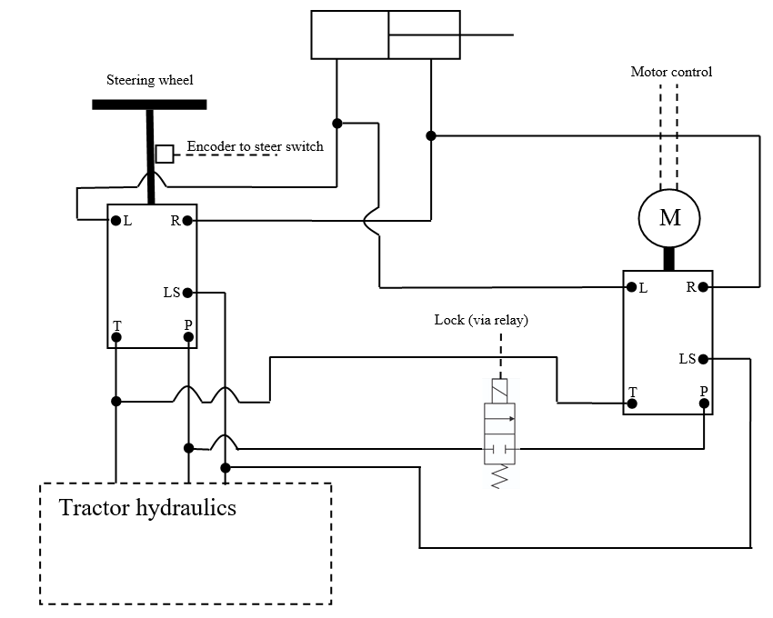
I am beginner in autostoring but determined to create a working device. I was thinking about how to connect to the hydraulic system and came up with an additional orbitrol driven by an electric motor that would be included in the system using a solenoid valve, a cheap flow divider used in front loaders cost about $ 50, orbitrol can be bought for $ 100 so it would be a cheap solution, what do you think about it I’m from Poland and I don’t know English well so I hope you can understand what I mean. Below is the schematic diagram of my solution.
I think its a pretty good idea… But i guess the steering wheel is already connected to an orbital so the fine control you get from a pwm valve is still a much better way to control - albeit the $$$ is much higher.
Perhaps an orbitol that had a much lower volumetric output per turn - ie, it would spin much faster then you could do by hand. Better for a motor to spin faster and easier to control. You could also run a shaft encoder for speed feeback. They slip fluid so it would still need a WAS, but short term, an shaft encoder would be very workable, WAS would be long term correction
You could use a simple 2 way valve to bypass the second orbital (ie. connect P to T on orbital 2) instead of breaking into the main circuit. This would then leave the main circuit reasonably standard. I don’t think orbitals rotate under back pressure on the output lines do they?
It may rotate and not rotate but they are certainly not 100% tight and leaving an open line to the cylinder with automatic control may affect accuracy. After thinking, I think that instead of a 4-way electrically controlled valve you can give a controlled check valve (so-called lock).
On page 8 diagram inside orbitrol OSPD ON Open center Non-reaction
I am start building with 2 orbitrol , but with DC servo motor (full control with quadrature encoder) , gear 1:10 and danfoss OSPC ON non reaction. Writing program for dsPIC30F4012, trapezoidal move profile, control with serial port.
I believe your setup could work.
If orbitrols are non reacting type you dont need lock valves.
If they are reacting type, you need a lock valve for both, or steering wheel or dc motor will spin!
This type is an example: Marchesini 3/8" Dual Pilot Operated Check Valve
2 Likes
Providing non reacting orbital units are used it would be a pretty safe system too. No valve to stick creating a dangerous situation. Existing system would work in almost any failure scenario apart from pipe breakage. Much safer than a valve that locks out the existing system with its obvious failure issues.
1 Like
I think that first I will make a simple system without any blocking valves and check if the orbitrols that I have in the tractors will rotate, if it works then there is nothing to complicate.
1 Like
I am building something like this.
1 Like
That is exactly how I would pipe it. Just a thought, that your diagram made me think, does an orbital unit mind possible full pressure on the ‘T’ line? I’m thinking about the shaft seal area and if it is drained to ‘T’. A scenario that will occur at full lock when it is reached using the motor driven orbital.
I am not sure if you can load the T output in every orbitrol. I have used in many of my projects to use the T output to power other receivers and there were no problems with the shaft sealing. In most orbitrol, the catalog card allows this option.
@baraki , you test 2 open centre orbitrol in series , and working , no problem?
In an older tractor that did not have power steering, I installed orbitrol by connecting it to the main lift pump, the pump fed oil to the P input on the orbitrol and to the T output I connected the lift and external hydraulic valves. This solution has been working for many years and there are no problems with sealing on the orbitrol shaft.
1 Like
I suppose the easy way to test if onboard orbitol is locked would be to drive over something where the wheel would normally force the steering wheel. “Hitting a curb” kind of concept. Would be a simple non invasive test.
@grabik interesting project. Perhaps start a Project and post your progress? Even a few pictures and lines would be great.
1 Like
I thought i would be clever one day and mount the wheel angle sensor right on the rotary jack that moved the tie-rods on the JD. Seems like the perfect solution. However, I could not get that thing to steer in a straight line to save my life. It would wander a lot. Put the sensor back on the wheel kingpin, worked perfectly.
I say this because even if you have a tiny bit of slack (and i’m sure there is) between the orbitol and the actual wheel, it will never be the right angle. Also on sidehills, the wheels are forced in directions you simply can’t measure from the orbitol. So, I think you also need to include the WAS as part of feed forward design or use the encoder as feed forward, but still rely on the WAS for final position.
I say this because it was a very frustrating couple of weeks for me. It would be so nice to just use the one measurement, but the final wheel angle is critical
I think that an encoder on the motor is not necessary since we put the steering sensor on the steering axle. Feedback from the final effect is the most important here.
It makes for very effective control to quickly initially position it though. That’s where feed forward comes in with pid
In your opinion, is the installation of the steering sensor on one steering knuckle not subject to too much an asymmetry error? The steering is on a trapezoid, which causes a different angular movement of a single wheel to the right and another to the left.
Wouldn’t it be better to give potentiometers on the right and left wheel and connect it properly to get a symmetrical result left and right?
Depending on the linkage to the sensor, you can remove a lot of the ackerman angle. There is another thread talking about that. AOG is based on a bicycle model - meaning a center steering wheel only. Different length arms and careful mounting i found has eliminated most of the difference. Just turning left to right fully, and you can see the difference and any change you make.
Waking up this old thread since I had a similar idea. How did it work out?
Looking at our old Case MX100C we have an LS based orbitrol. It would be rather cost effective to add an extra orbitrol in order to skip the electric motor for the steering wheel. I made a simple sketch for a add-on motordriven orbitrol. Any input would be appreciated…