Good day, I’m new to AOG so I’m not sure what I’m missing here. The ADS1115’s That I get in the mail don’t resemble the rest of yours. It seems like they have been updated. But now I see the new All in One PCB is designed for what I thought was the old ADS1115. I’ve ordered directly from Adafruit, and I got the unit that is pictured on their site. I then saw the difference and ordered one from Digikey as theirs was pictured like the “old one”. Well I ended up getting this “new version” that Adafruit had originally sent me. Any suggestions?
I’ve attached the links to the units that I ordered.
ADS1115 16-Bit ADC - 4 Channel with Programmable Gain Amplifier [STEMMA QT / Qwiic] : ID 1085 : $14.95 : Adafruit Industries, Unique & fun DIY electronics and kits
1085 Adafruit Industries LLC | Development Boards, Kits, Programmers | DigiKey
The new one should work fine. Looks to me like you could put the pin headers on the side of the breakout board that has vin, gnd, scl, sda, and alert and solder that to the all-in-one board using the left-most 5 pin holes. Then use wires to go from the A0,A1, A2, and A3 holes on the other side of the breakout to equivalent holes on the all-in-one board. You’d likely want to support the board with some hot glue or something since the mount holes and standoffs wouldn’t work.
I’d bring it up with Digikey, ask them what’s up with the incorrect picture. You won’t need an extra ADS for the new dual PCB if you get one with the onboard surface mounted ADS unless you damage it somehow, then an external ADS board is suppose to work as a replacement.
1 Like
Sounds good, I think I’ll try and return these for I plan on using the new All in One. And Thank you for the jumper suggestion, I’ll try that on a board I have here already.
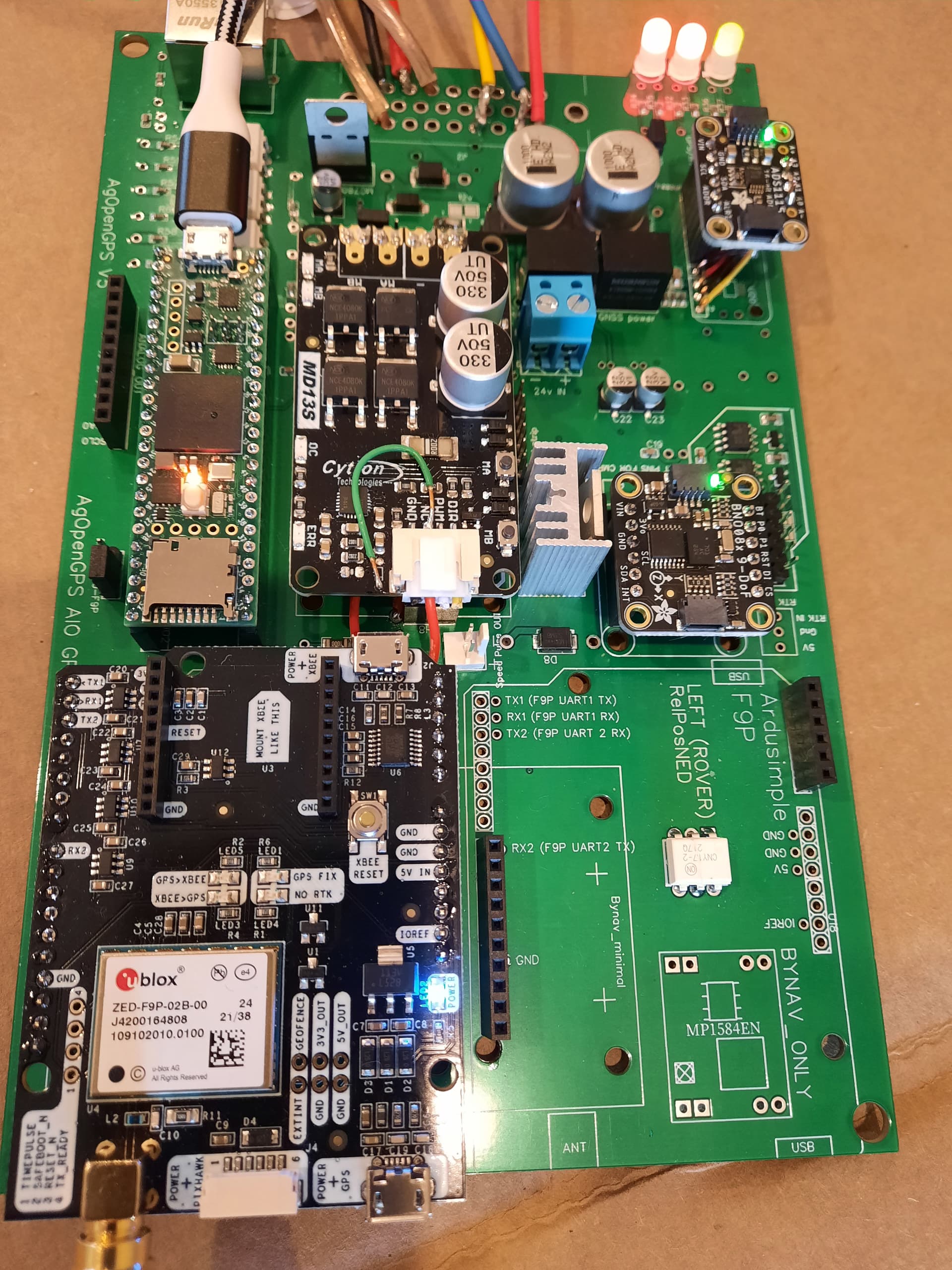
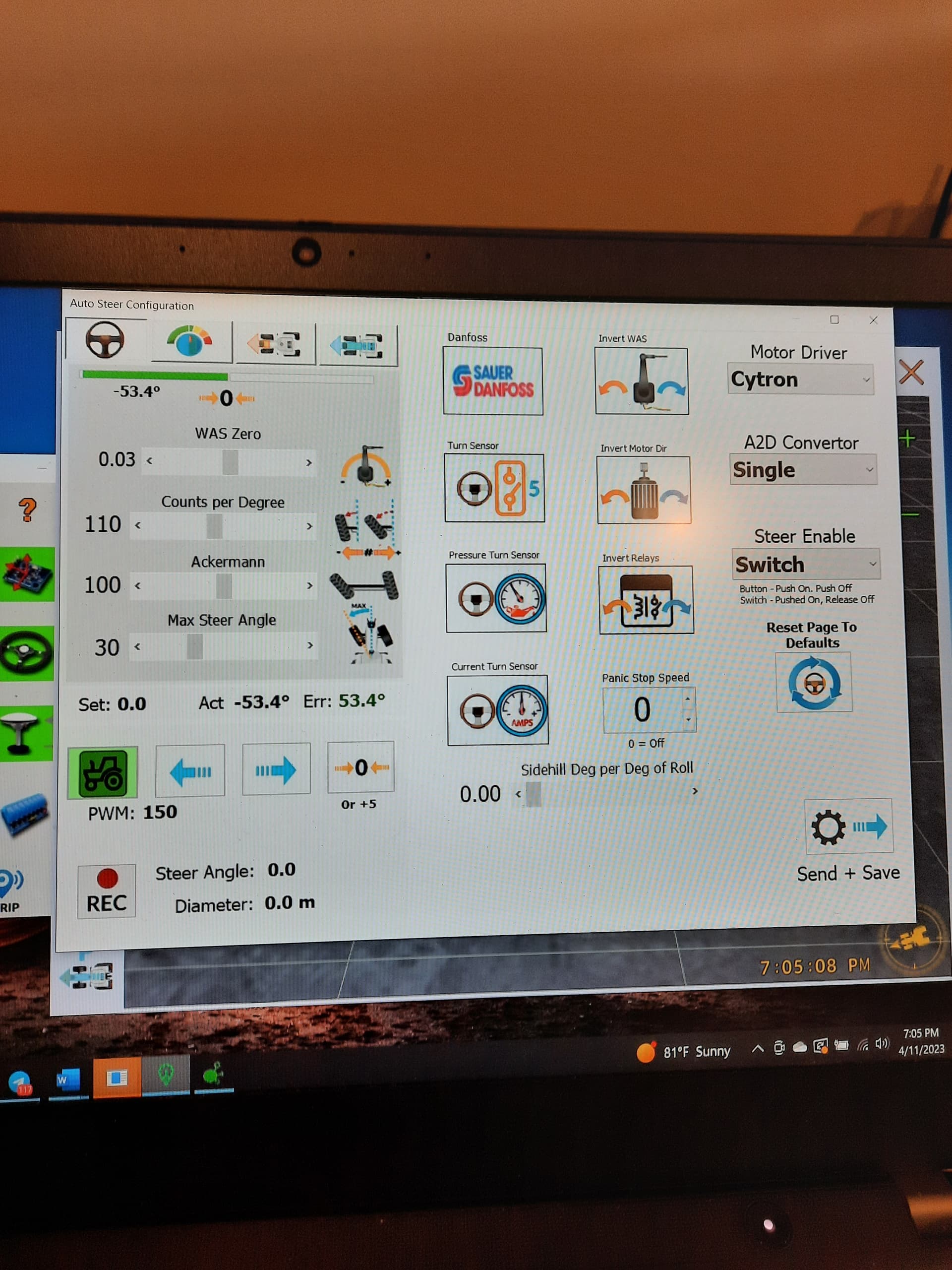
This is my first build of an AOG system. I’ve started with a 2.4 AIO board, and I also have the newer style ADS1115 as Jerry67 mentioned above. I followed torriem’s advice above to mount the ADS1115 with the 5 pins vin, gnd, scl, sda, and alert, and to also solder a wire between the corresponding a0, a1, a2, a3 holes on the ADS1115 and the holes in the board. I have my WAS RQH 100030 connected. I’ve tested the WAS with the signal wire disconnected from the board, and the WAS works. With it connected, and with a GPS Fix, I’m not able to get any reaction in AgOpenGPS. I am using 5.7.1 ino.hex, and AgOpenGPS. Is there something else I need to do to test my WAS with this board? The USB connection to teensy in the picture is not being used
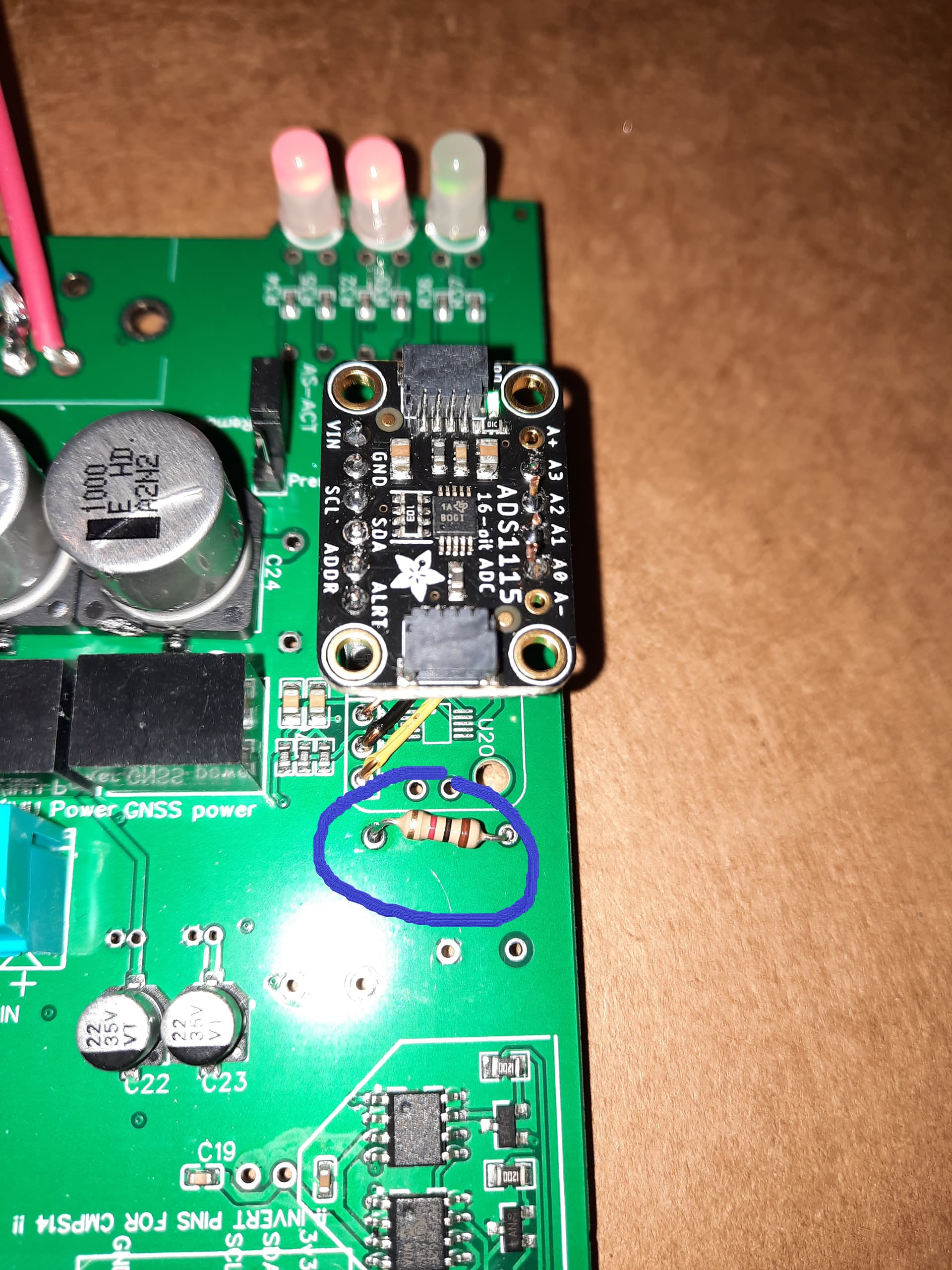
Good news, I was able to get this working. Patrick from Telegram showed me that I was missing a 1K resister as shown here.
3 Likes